Injection device

a technology of injection device and injection tube, which is applied in the direction of medical devices, intravenous devices, medical devices, etc., can solve the problems of patient trouble, liquid leakage problem, and not being free of risk, and achieve the effect of facilitating us

Inactive Publication Date: 2009-05-19
JCR PHARMA
View PDF12 Cites 16 Cited by
  • Summary
  • Abstract
  • Description
  • Claims
  • Application Information

AI Technical Summary

Benefits of technology

[0015]Against the above-mentioned background, the objective of the present invention to provide an injection device that is designed to receive therein a two-compartment syringe and used to perform a dissolution process of the pharmaceutical agents contained in it and then multiple portionwise injections, wherein the injection device unfailingly prevents the slidable rear wall from being abruptly pressed in during the process of dissolving the contained pharmaceutical agents, thereby guaranteeing proper mixing of the pharmaceutical agents, and then allows multiple portionwise injections of a desired volume, wherein the injection device itself can be repeatedly used by removing an exhausted two-compartment syringe and loading a fresh one, and wherein the injection device makes it easy to adjust the volume to be injected accurately on a smaller scale.
[0022]wherein the piston rod and the sleeve are so configured and arranged that rear part of the piston rod may abut on the sleeve and be thus prevented from advancing further in the forward direction from the position where it abuts on the sleeve.
[0039]According to the present invention as defined above, since it is a spring that presses in the slidable rear wall for mixing the pharmaceutical agents in a two-compartment syringe, the slidable rear wall is prevented from being abruptly pressed in, and, thereby, proper mixing of the pharmaceutical agents is guaranteed. And, as the amount of the distance up to which the piston rod is pressed in is controlled by rotating the sleeve which is in screw engagement with the barrel portion, the device makes it easy to perform repeated multiple portionwise injections, in a predetermined amount, of the injectable liquid prepared by the mixing. Especially, if the device is further provided with a sighting means and the numerals pointed to by it are marked on the sleeve, the device allows a user to visually know with ease the position of the sleeve required to inject a predetermined volume of injection. Further, the injection device of the present invention allows repeated use, and therefore when a two-compartment syringe has been exhausted, the device can be reused with ease, after removing the exhausted two-compartment syringe and inserting a fresh one, for performing mixing of the pharmaceutical agents and then multiple portionwise injections, as done in the first round of injections.

Problems solved by technology

However, devices that allow patients to abruptly press in the slidable rear wall in the process of mixing / dissolving of the pharmaceutical agents (see Patent Documents 1 and 2) are not free of the risk of causing the above-mentioned problem of liquid leak.
Though such devices are known that are designed so that the piston rod is slowly advanced by rotating a screw and the slidable rear wall is thereby slowly pressed in (see Patent Documents 4 and 5), it is quite troublesome for patients who daily handle such devices that they must rotate the screw with their hand in order to press in the piston rod.
Though this device successfully eliminates the risk of being handled abruptly in mixing of the pharmaceutical agents contained in a two-compartment syringe, it is of a complex structure and consists of a number of components, and, further, it is difficult with this type of device either to provide such steps for adjustment precisely and at short intervals or to make it adapted to repeated multiple portionwise injections, since in the device, control of injection volume is done by engagement of steps provided in a helical arrangement around the thin injector rod with the rib provided in the inside of the plunger.
Therefore, with this injection device, if no improvement is made, it is not easy to restore the initial condition of the device (where the spring is locked), and so the device at least is inconvenient for patients who repeatedly handle it by themselves.[PATENT DOCUMENT 1] U.S. Pat. No. 4,874,381[PATENT DOCUMENT 2] U.S. Pat. No. 6,053,893[PATENT DOCUMENT 3] U.S. Pat. No. 6,419,656[PATENT DOCUMENT 4] U.S. Pat. No. 4,968,299[PATENT DOCUMENT 5] U.S. Pat. No. 5,080,649[PATENT DOCUMENT 6] U.S. Pat. No. 6,793,646

Method used


Image

  • Injection device
  • Injection device
  • Injection device

Examples


examples

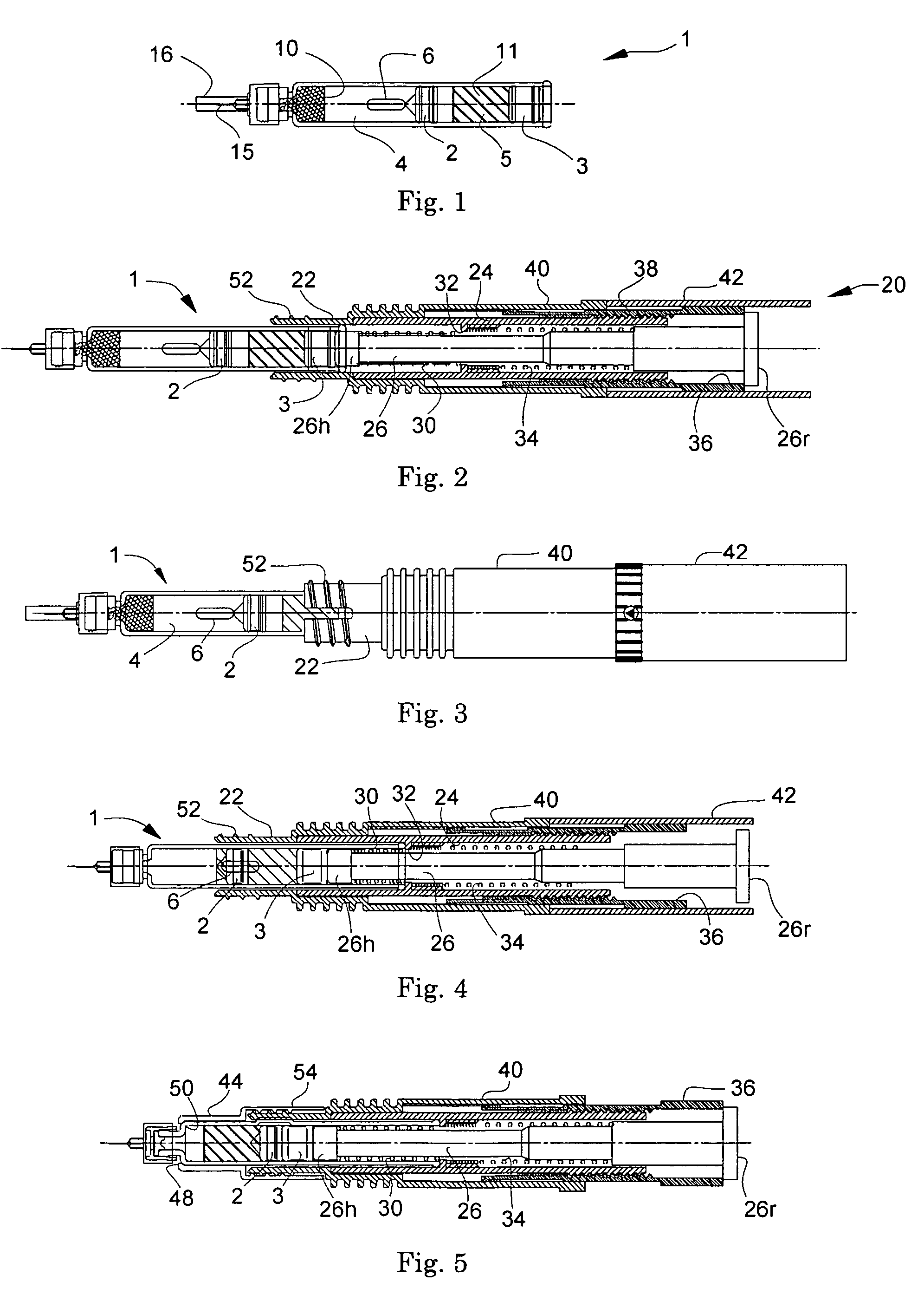
[0063]The present invention is described in further detail below with reference to a typical example. However, it is not intended that the present invention be limited to the example.

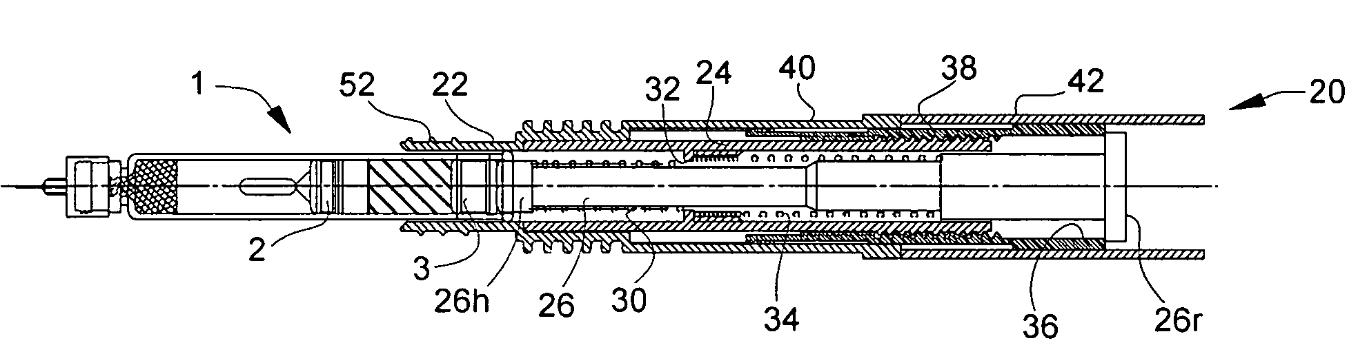
[0064]FIG. 2 illustrates a cross section of the injection device 20 in the example, with the two-compartment syringe shown in FIG. 1 just starting to be inserted in a rear end-first manner, and FIG. 3 illustrates a side view of it. With regard to these figures, the leftward direction in the drawing represents the upward direction in actual operation. In FIG. 2, both of those indicated with numerals 22 and 24 are cylindrical and parts of the barrel portion, which, combined together, form a cylindrical barrel portion. A piston rod 26 is passed through the barrel portion. The piston rod 26 includes a head 26h having an enlarged diameter formed at and near the front end, and a plate 26r having an enlarged diameter formed at the rear end. In association with the piston rod 26, a coil spring 30 (front spring)...


PUM


Abstract

An injection device is disclosed which is designed to receive therein a two-compartment syringe, and to be used to mix the pharmaceutical agents and then conduct injections. The injection device comprises a cylindrical barrel portion so configured that the two-compartment syringe can be inserted therein in a rear-end first manner, a piston rod for pushing the slidable rear wall to advance, a front spring that is compressed, when the two-compartment syringe is inserted, and then push back the piston rod in the forward direction, and a sleeve which can be shifted back and forth and is provided by screw engagement with the outer surface of the rear part of the barrel portion to block the forward movement of the piston rod.

Description

FIELD OF THE INVENTION[0001]The present invention relates to an injection device, in particular to an injection device into which a two-compartment syringe containing pharmaceutical agents in its two compartments separately from each other is loaded, and with which mixing of the pharmaceutical agents and their injection are to be performed.BACKGROUND OF THE INVENTION[0002]To maintain their stability, injectable peptide preparations, e.g., those of growth hormone, are provided in two-component forms consisting of a dried pharmaceutical component prepared by lyophilization, for example, and a liquid pharmaceutical component (a solvent liquid such as a buffered solution) in which the former component is dissolved to give an injectable liquid. And, to allow patients' easy and reliable handling of them, two-compartment syringes (also called dual-chamber cylinder ampoules) are widely employed, e.g., for human growth hormone preparations, in which those two components are contained separat...

Claims


Application Information

Patent Timeline
Patent Type & Authority Patents(United States)
IPC IPC(8): A61M37/00
CPCA61M5/2448A61M5/3155A61M5/31551A61M5/3158A61M2005/3123
Inventor SUGITA, KOUICHIMATSUMOTO, HIROSHI
Owner JCR PHARMA
Why Eureka
Try Eureka