Rotary cutting tool with cutter blade regulation mechanism

A cutting tool and rotary technology, which is applied in the field of rotary cutting tools, can solve the problems of tool chatter, rough workpiece surface, burr and shortened tool life, and achieve the effect of easy maintenance and cost saving

Active Publication Date: 2007-10-17
SUMITOMO ELECTRIC HARDMETAL CORP
View PDF3 Cites 8 Cited by
  • Summary
  • Abstract
  • Description
  • Claims
  • Application Information

AI Technical Summary

Problems solved by technology

Any axial misalignment of the insert cutting edge can result in rougher machined surfaces on the workpiece, tool chatter, burrs and / or reduced tool life

Method used


Image

  • Rotary cutting tool with cutter blade regulation mechanism
  • Rotary cutting tool with cutter blade regulation mechanism
  • Rotary cutting tool with cutter blade regulation mechanism

Examples


Embodiment Construction

[0043] Next, the rotary cutting tool of the present invention will be described with reference to FIGS. 1 to 6 .

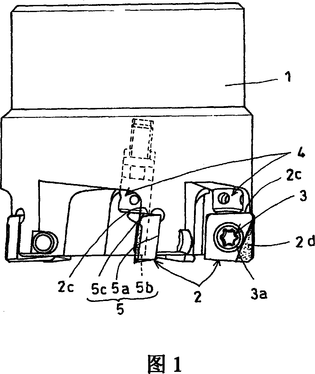
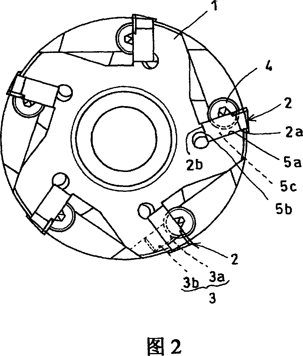
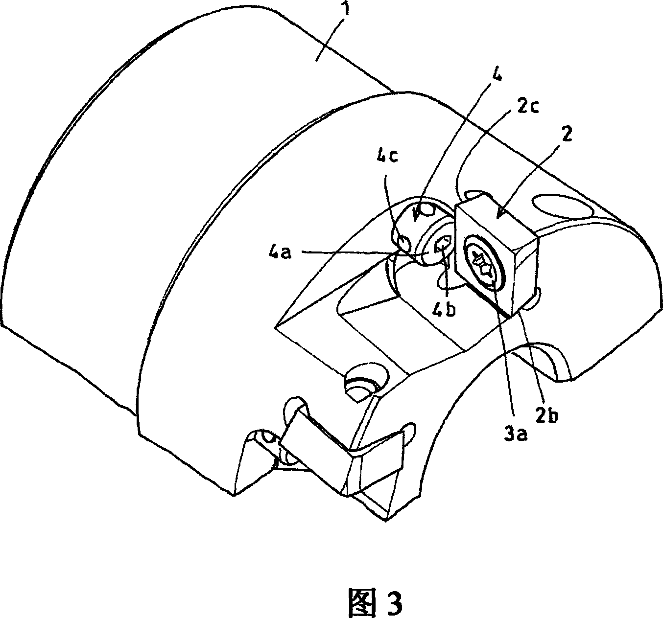
[0044] 1 to 4 show a rotary cutting tool according to a first embodiment of the present invention. The rotary cutting tool shown in the figure is an angle milling cutter, including: a tool body 1; a disposable blade 2; a clamping device 3, which respectively fixes a blade 2 on the tool body 1; and an adjusting screw, which is used to adjust each Position of blade 2.

[0045] A blade mounting groove 5 is formed in the outer periphery at the top end of the tool body 1 . As shown in Figure 4, each blade mounting groove 5 has three seating surfaces, comprising: seating surface 5a, the back 2a of each blade 2 is seated on the seating surface 5a; seating surface 5b, the side 2b of each blade 2 facing the tool axis seated on the seating surface 5b; and a seating surface 5c on which the side 2c of each blade 2 facing the base end of the tool is seated. Thus, the blade ...


PUM


Abstract

A rotary cutting tool capable of stably performing roughing and finishing and, when a cutter blade play accuracy is requested, capable of securely performing cutter blade play regulation by a simple mechanism in a short time. A plurality of blade grooves (5) are formed at the tip outer periphery of a cutter body (1), and throw-away tips (2) are fixedly fitted to the blade grooves (5) by using clamp means (3). Also, axially threaded cutter blade play regulation screws (4) are fitted to the blade groove formed parts of the cutter body (1). Three seating faces for positioning and arresting the throw-away tip (2) in three directions are formed on each of the blade grooves (5). The head top face of the cutter blade play regulation screw (4) is displaced forward and backward from the seating face (5c) for axial positioning of the cutter blade groove so that the axial positioning of the throw-away tip (2) can be performed by using any of the seating face (5c) and the head top face of the cutter blade play regulation screw. Also, cutter blade play regulation can be performed only for a blade for which the cutter blade play regulation is requested.

Description

technical field [0001] The present invention relates to rotary cutting tools, such as face mills or angle mills, having means for adjusting the axial position of individual throwaway inserts relative to the tool body and relative to each other. Background technique [0002] In finish milling, it is important to arrange cutting edges of disposable inserts with high positional accuracy. Any axial misalignment of the insert cutting edge can result in roughened workpiece surfaces, tool chatter, burrs and / or reduced tool life. [0003] Various proposals have been made regarding adjusting or eliminating such axial offset of the insert cutting edge, including those disclosed in Patent Documents 1 to 4 below. [0004] Patent Document 1: Japanese Patent Laid-Open No. 2001-252813A [0005] Patent Document 2: Japanese Utility Model Publication No. 7-27719 [0006] Patent Document 3: Japanese Utility Model Publication No. 3064324 [0007] Patent Document 4: Japanese Patent Laid-Open...

Claims


Application Information

Patent Timeline
Patent Type & Authority Applications(China)
IPC IPC(8): B23C5/24B23C5/06
CPCY10T407/192Y10T407/1912B23C5/2424B23C5/2406B23C5/2472B23C5/24B23C5/2243B23C5/2208
Inventor 水谷正则
Owner SUMITOMO ELECTRIC HARDMETAL CORP
Why Eureka
Try Eureka