Printer and printing method

A technology of a printing device and a printing head, applied in directions such as printing, can solve the problems of lack of convenience for users, increased waiting time, frequent and other problems, and achieve the effects of reducing printing density unevenness and streaks, reducing time, and preventing overheating

Inactive Publication Date: 2007-10-17
SONY CORP
View PDF4 Cites 9 Cited by
  • Summary
  • Abstract
  • Description
  • Claims
  • Application Information

AI Technical Summary

Problems solved by technology

[0016] Especially, when many high-density images such as night scenes are printed at high speed, the thermal head will have a large heat value, which will cause frequent stops and cooling of the thermal head, and cause an increase in the length of time the user has to wait
That is, conventional thermal printers lack convenience for users

Method used


Image

  • Printer and printing method
  • Printer and printing method
  • Printer and printing method

Examples


no. 1 example

[0106] Similar to the first embodiment, the above-described printer 1 can be a standard-speed printing mode for ordinary printing, and a low-speed printing mode specially set when the temperature of the thermal head 108 becomes higher due to stored heat.

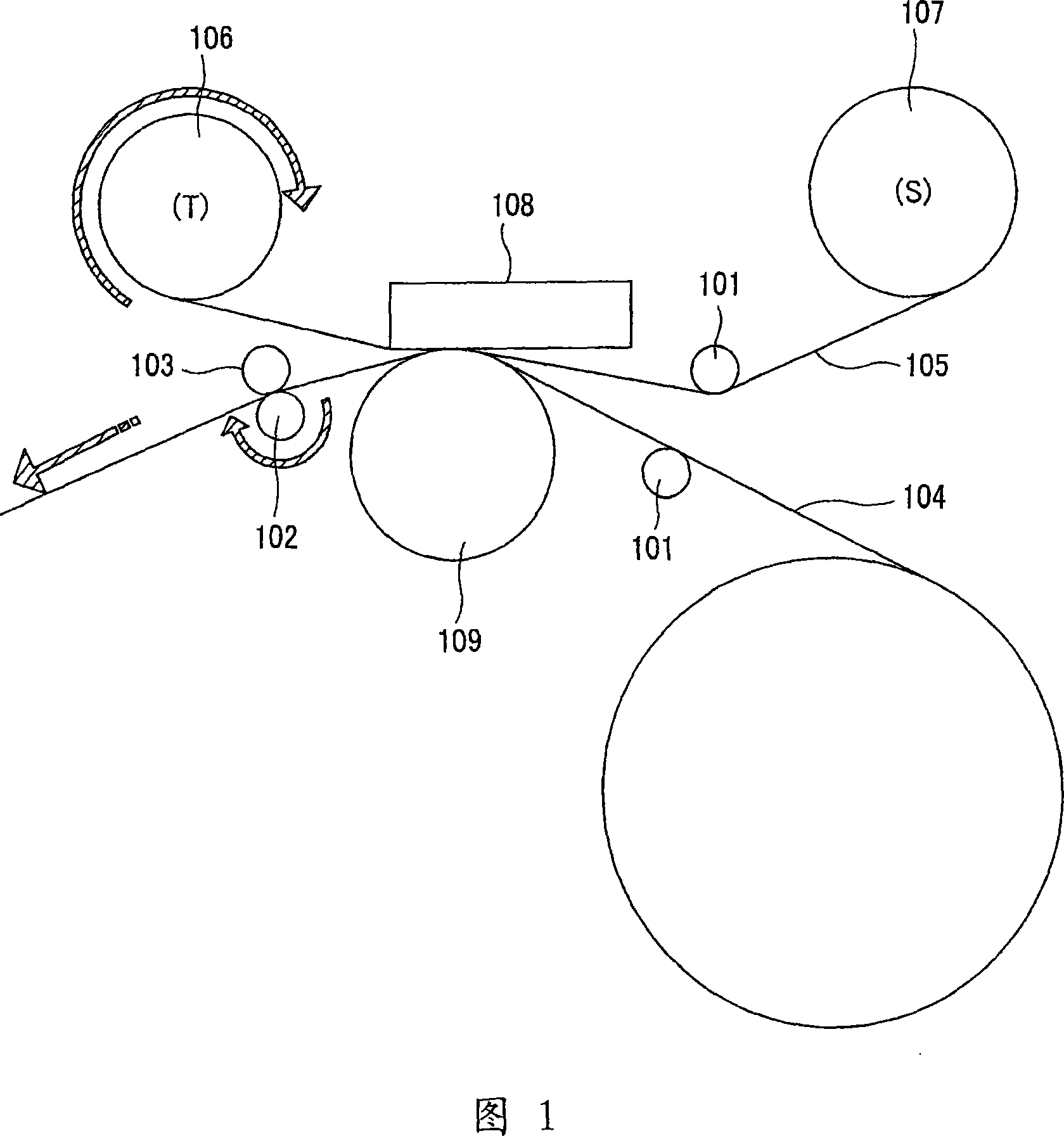
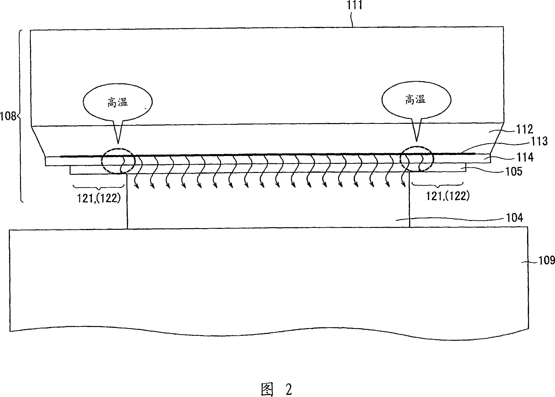
[0107] Standard speed printing mode enables printing at high speed as with a conventional printer. The instantaneous heat value per unit area of ​​the heating element 113 is higher than that of a conventional printer, and the conveying speed of the printing medium 104 is also set higher than that of a conventional printer. On the other hand, the low-speed printing mode makes the instantaneous calorific value per unit area of ​​the heating element 113 less than the standard speed printing mode, and the conveying speed of the printing medium 104 is lower than the standard speed printing mode, so as to put more pressure on the thermal head. The heat stored in 108 is dissipated to the printing medium 104 and the transfer wheel 1...


PUM


Abstract

There is provided a printing device using a thermal head having heating elements in the line state in the direction vertical to the feed direction of a printing medium as a printing head. According to the both ends of the line of image data to be printed or pixel data in the vicinity, accumulation data on the thermal head (108) of each line is calculated based on the accumulation data on the preceding line. The accumulation data on each line is compared to a predetermined value. When any of the accumulation data is greater than the predetermined value, energy of the heating element (113) is lowered and the image data is printed on the printing medium (104) with the lowered energy of the heating element (113). Thus, even when a high-speed printing is performed, it is possible to prevent generation of a high-temperature portion at the both ends of the thermal head causing concentration irregularities in the printed image.

Description

technical field [0001] The present invention relates to a printing apparatus and method in which a thermal head having heat generating elements linearly arranged perpendicular to a conveying direction of a printing medium is used as a printing head. [0002] This application claims the benefit of Japanese Patent Application Nos. 2004-274238 and 2004-274239 filed in the Japan Patent Office on September 21, 2004, which are hereby incorporated by reference in their entirety. Background technique [0003] Conventional thermal printers using a thermal head include sublimation printers, fusion printers, thermal printers, and the like. The thermal head used in these printers includes a plurality of heat-generating elements arranged linearly, the energization of each of these heat-generating elements is controlled corresponding to the gray scale, and the thermal energy thus generated is used in different types of printing print on the media. [0004] Next, the thermal printer will...

Claims


Application Information

Patent Timeline
Patent Type & Authority Applications(China)
IPC IPC(8): B41J2/36B41J2/355
Inventor 高野洋明滝泽直树
Owner SONY CORP
Why Eureka
Try Eureka