Laminated heat exchanger

A technology of heat exchangers and laminates, which is applied in the direction of heat exchange equipment, indirect heat exchangers, heat exchanger types, etc., can solve problems such as freezing of condensed water, and achieve the effect of avoiding extreme drops and reducing manufacturing costs

Inactive Publication Date: 2007-10-24
SHOWA DENKO KK
View PDF1 Cites 10 Cited by
  • Summary
  • Abstract
  • Description
  • Claims
  • Application Information

AI Technical Summary

Problems solved by technology

Also, in the area where the air velocity is low on the rear side, condensed water may freeze on the surface of the refrigerant flow tube and the fins

Method used


Image

  • Laminated heat exchanger
  • Laminated heat exchanger
  • Laminated heat exchanger

Examples


Embodiment 1

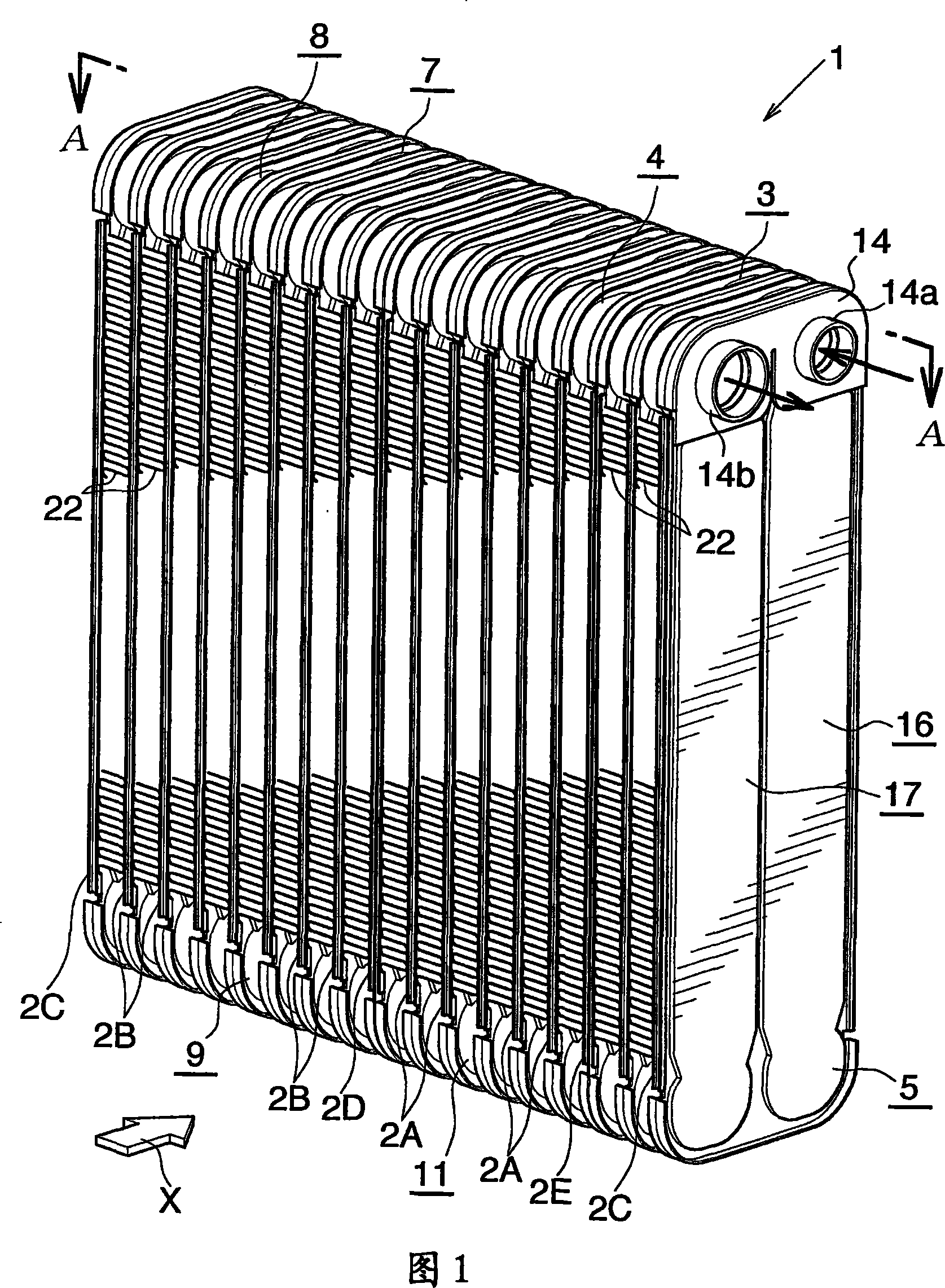
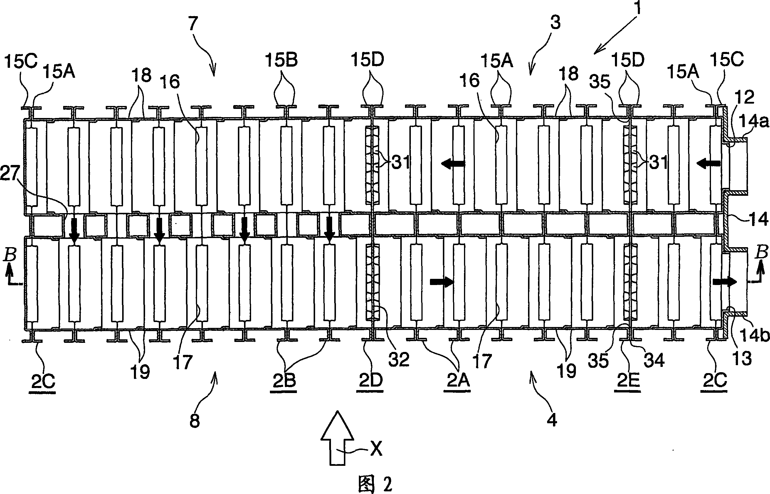
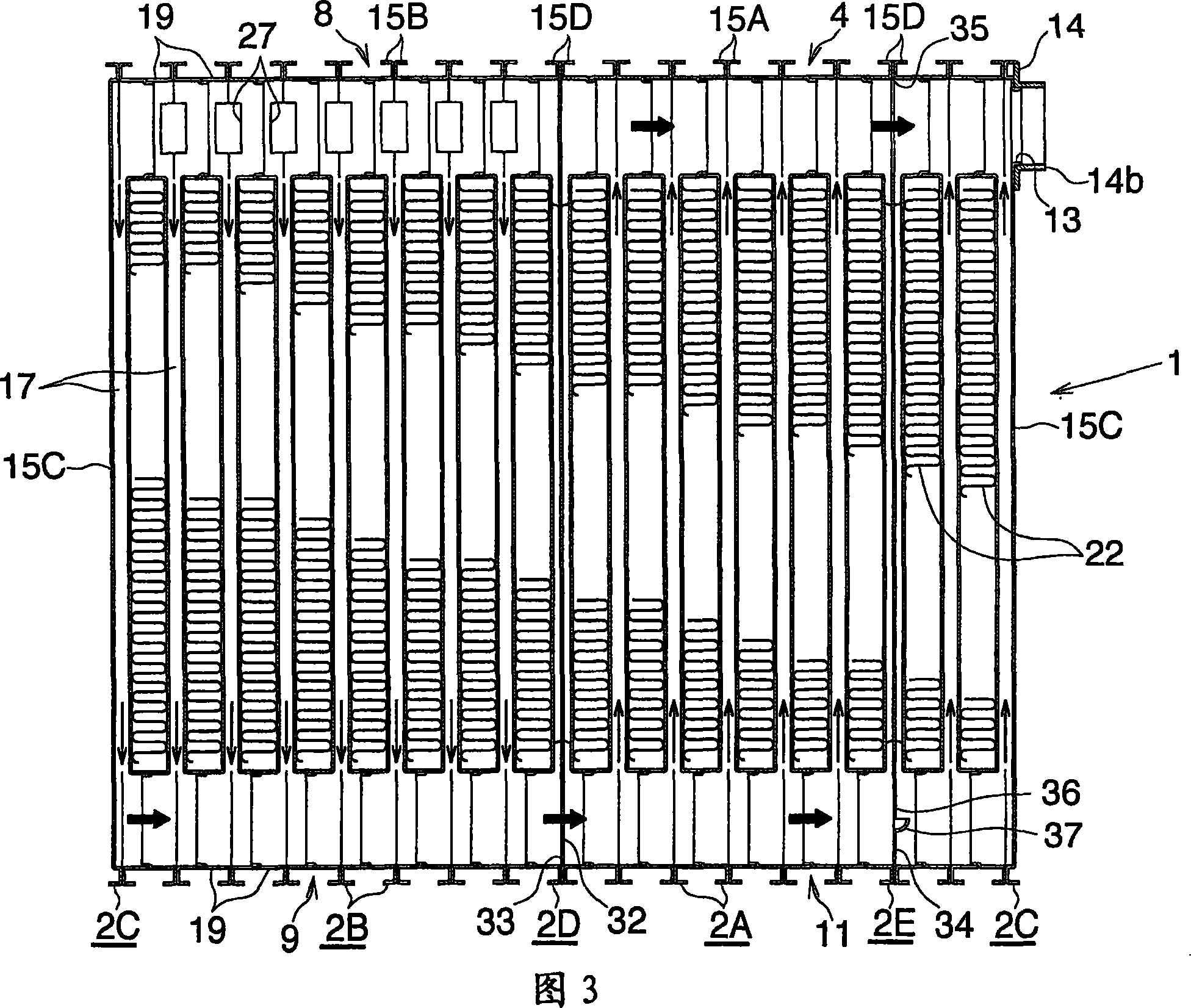
[0052] 1 to 10 show this embodiment.

[0053] 1 to 3 show the overall structure of the evaporator of Embodiment 1; FIGS. 4 to 9 show the structure of the main part of the evaporator; and FIG. 10 shows the flow of refrigerant in the evaporator.

[0054] 1 to 3, the evaporator (1) is designed such that a plurality of flat hollow parts (2A), (2B), (2C), (2D) and (2E) are arranged in a stacked manner in the left and right direction and combined in Together, each flat hollow member has a vertically elongated rectangular shape while their width extends in the front-rear direction (air flow direction). The evaporator (1) includes: a refrigerant inlet header section (3) extending in the left-right direction; a refrigerant outlet arranged behind the refrigerant inlet header section (3) (upstream relative to the air flow direction) and extending in the left-right direction The header section (4); the first intermediate header section (5) arranged under the refrigerant inlet header sect...

Embodiment 2

[0072] 11 to 15 show this embodiment.

[0073] 11 shows the overall structure of the evaporator of Embodiment 2; FIGS. 12 to 14 show the structure of the main part of the evaporator; FIG. 15 shows the flow of refrigerant in the evaporator.

[0074] Referring to Fig. 11, the evaporator (40) is designed in such a way that a plurality of flat hollow parts (41A), (41B), (41C) and (41D) are arranged in a stacked manner in the left and right direction and combined together, the flat hollow Each of the parts has a vertically elongated rectangular shape while their width extends in the front-rear direction (air flow direction). The evaporator (40) includes: a refrigerant inlet header section (42) extending in the left-right direction; a refrigerant outlet header section (43) extending from the refrigerant inlet header section (42) and located on the right side thereof and extending in the left-right direction; a first intermediate header section (44) arranged in front of the refriger...


PUM


Abstract

An evaporator 1 implemented by a laminated heat exchanger has a refrigerant inlet header section 3, a refrigerant outlet header section 4, and a plurality of intermediate header sections 5 to 11. Among the header sections 3 to 11, the sixth intermediate header section 11 has a refrigerant channel which allows flow of refrigerant in the longitudinal direction thereof and whose downstream end with respect to the refrigerant flow direction is closed, and causes refrigerant to dividedly flow into a plurality of refrigerant flow tube portions. The refrigerant that has flown into the refrigerant inlet header section 3 from a refrigerant inlet 12 flows into the refrigerant outlet header section 4 through the refrigerant flow tube portions and through the intermediate header sections 5 to 11 and flows out from a refrigerant outlet 13. A resistive plate portion 38 is provided within the sixth intermediate header section 11 so as to block the refrigerant channel thereof extending in the longitudinal direction thereof. A resistive hole 36 is formed in the resistive plate portion 38 so as to impart resistance to refrigerant that flows through the refrigerant channel. When this laminated heat exchanger is applied to an evaporator of a vehicle air conditioner, temperature distribution of discharged air can be made uniform even when air-velocity distribution becomes nonuniform on the upstream side with respect to the air flow direction.

Description

[0001] Cross References to Related Applications [0002] This application is filed under 35 U.S.C §111(a) and is required under 35 U.S.C §119(e)(1) of provisional application 60 / 609,831 filed September 15, 2004 under 35 U.S.C §111(b) Filing date benefits. technical field [0003] The invention relates to a laminated heat exchanger, in particular to a laminated heat exchanger used as an evaporator in a vehicle air conditioner, which is a refrigeration cycle loaded in the vehicle. [0004] In the text and the appended claims, the upper, lower, left-hand and right-hand sides of Figures 1, 3 and 11 are referred to as "upper", "lower", "left" and "right", respectively. The downstream side of the air flow (direction indicated by arrow X in FIGS. 1 and 11 ) is referred to as "front", and the opposite side thereof is referred to as "rear". Background technique [0005] A laminated heat exchanger generally widely used as an evaporator of a vehicle air conditioner includes a plurali...

Claims


Application Information

Patent Timeline
Patent Type & Authority Applications(China)
IPC IPC(8): F28F9/02B60H1/32F25B39/02
CPCF28D1/0341F25B39/022F28D1/0333F28D2021/0085
Inventor 森大辅东山直久
Owner SHOWA DENKO KK
Why Eureka
Try Eureka