Multistage compression type rotary compressor

A rotary compressor and rotary compression technology, which is applied to rotary piston machines, rotary piston pumps, mechanical equipment, etc., and can solve problems such as unstable operation, noise, and flap beating of the second rotary compression unit

Inactive Publication Date: 2007-06-20
SANYO ELECTRIC CO LTD
View PDF2 Cites 4 Cited by
  • Summary
  • Abstract
  • Description
  • Claims
  • Application Information

AI Technical Summary

Problems solved by technology

[0008] In this way, if the discharge pressure of the first rotary compression unit and the discharge pressure of the second rotary compression unit are reversed, due to the pressure in the cylinder of the second rotary compression unit (the pressure of the refrigerant sucked into the second rotary compression unit (intermediate pressure)) It is higher than the discharge pressure (high pressure) of the second rotary compression unit applied as the back pressure of the vane, so the force of the vane acting on the roller side disappears, and the flapping of the vane of the second rotary compression unit occurs, causing noise. At the same time, the operation of the second rotary compression unit is also unstable.

Method used


Image

  • Multistage compression type rotary compressor
  • Multistage compression type rotary compressor
  • Multistage compression type rotary compressor

Examples


Embodiment 1

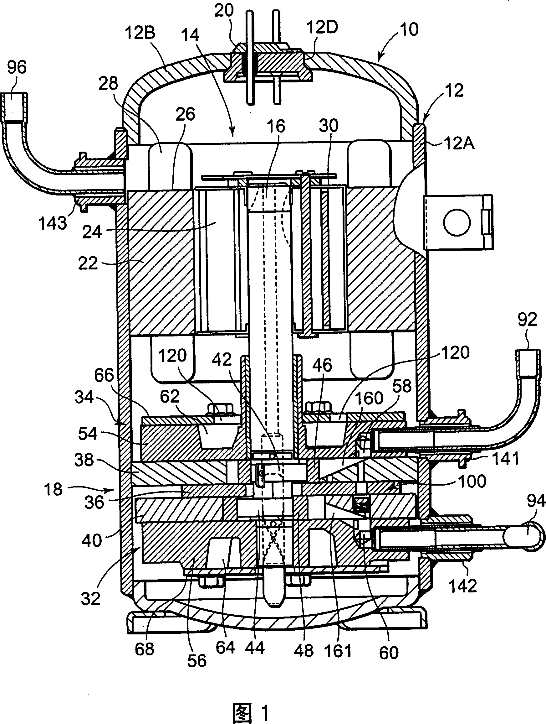
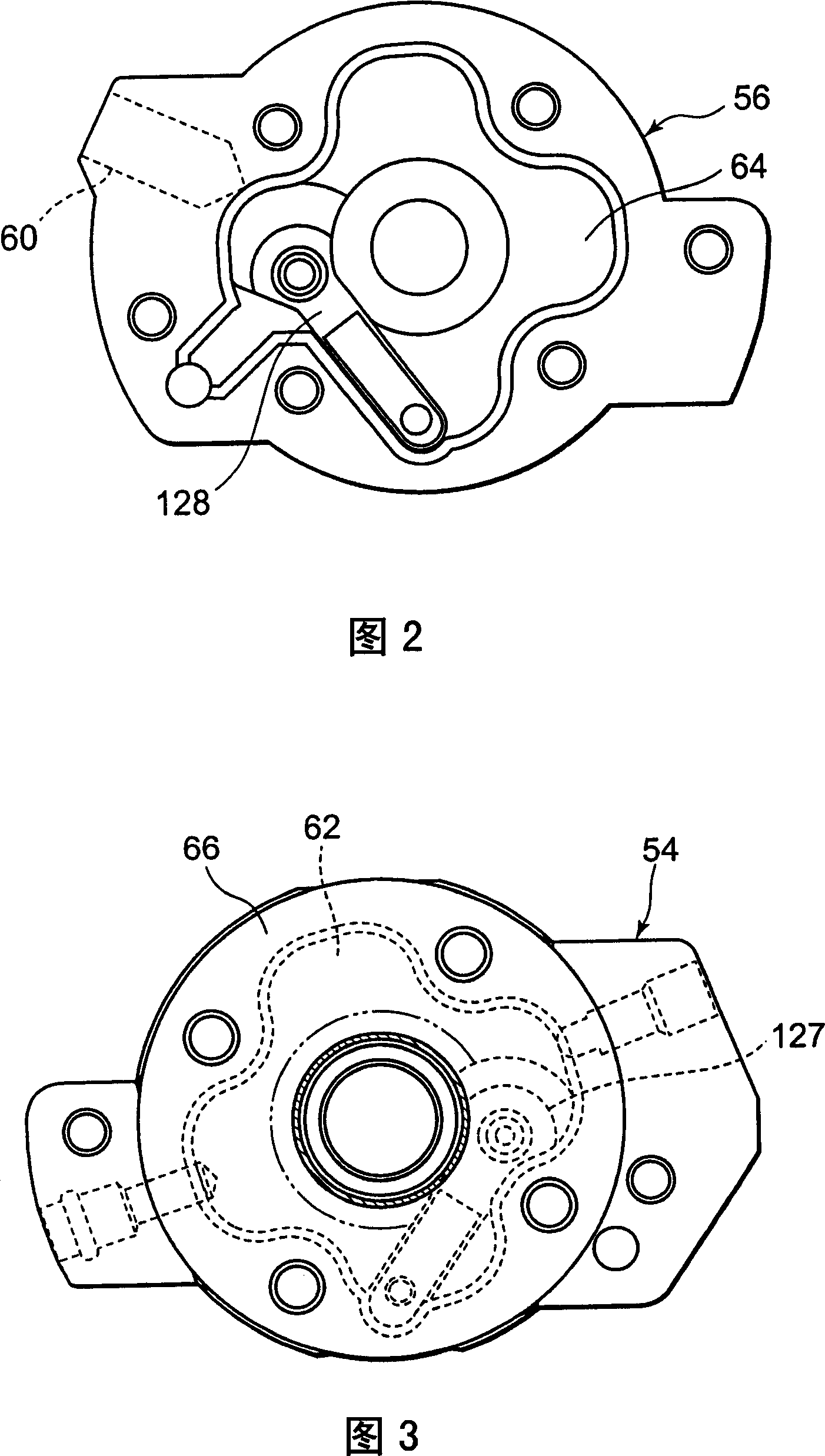
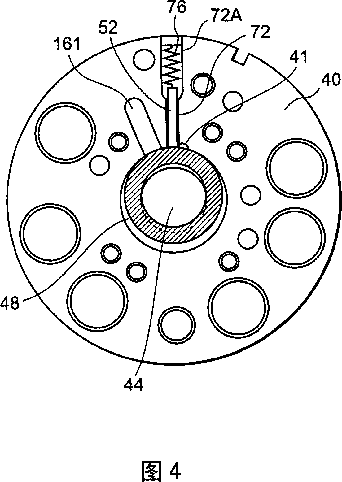
[0069] FIG. 1 is a longitudinal section side of an internal high-pressure multi-stage (two-stage) compression rotary compressor 10 provided with a first rotary compression unit 32 and a second rotary compression unit 34 as an embodiment of the multistage compression rotary compressor of the present invention. Figure 2 is a bottom view of the lower support member 56 of the first rotary compression unit 32, Figure 3 is a top view of the upper support member 54 of the second rotary compression unit 34 (the state of installing the upper cover), and Figure 4 is the first FIG. 5 is a bottom view of the lower cylinder 40 of the rotary compression unit 32 , and FIG. 5 is a plan view of the upper cylinder 38 as a cylinder constituting the second rotary compression unit 34 . In FIG. 1 , the rotary compressor 10 of the embodiment sucks and compresses the intermediate-pressure refrigerant gas compressed and discharged by the first rotary compression unit 32 into the second rotary compressi...

Embodiment 2

[0114] In addition, in the above-mentioned embodiment (Embodiment 1), the communication path 100 is formed in the sealed container 12 of the rotary compressor 10, and the suction port 161 and the suction port 160 are connected, but the communication path 100 of the present invention is not limited to this position. , as long as the intermediate-pressure area and the low-pressure area are connected, for example, it may also be formed outside the sealed container 12 . 9 and 10 show an example at this time. In addition, in FIG. 9 and FIG. 10 , the parts assigned the same symbols as in FIG. 1 to FIG. 8 have the same or similar effects, and description thereof will be omitted.

[0115] In this case, the communication path 200 is configured to communicate the refrigerant introduction pipe 92 and the refrigerant introduction pipe 94 through the valve device 117 so as to be openable and closable. The communication passage 200 is a passage for communicating the region of the intermedi...

Embodiment 3

[0125]11 is a third embodiment of the multi-stage compression rotary compressor of the present invention, showing an internal intermediate pressure multi-stage (two-stage) compression rotary compressor 10 including a first rotary compression unit 32 and a second rotary compression unit 34. sectional side view of . In addition, the bottom view of the lower support member 56 of the first rotary compression unit 32 is the same as that of FIG. The bottom view of the lower cylinder 40 of the compression unit 32 is the same as in FIG. 4 , and the top view of the upper cylinder 38 serving as a cylinder constituting the second rotary compression unit 34 is the same as in FIG. 5 .

[0126] In FIG. 11 , the rotary compressor 10 of the embodiment sucks and compresses the refrigerant gas at an intermediate pressure compressed by the first rotary compression unit 32 into the second rotary compression unit and discharges it into the hermetic container 12, and then discharges it. The intern...


PUM


Abstract

An object is to provide a high inner pressure type multistage compression rotary compressor capable of avoiding beforehand generation of vane fly of a second rotary compression element and realizing a stabilized operation, the rotary compressor includes a communication path which connects an intermediate pressure region to a region having a low pressure as a suction pressure of a first rotary compression element; and a valve device which opens or closes this communication path, the rotary compressor applies a high pressure as a back pressure of an upper vane, and this valve device opens the communication path in a case where a pressure difference between the intermediate pressure and the low pressure increases a predetermined upper limit value before the intermediate pressure reaches the high pressure.

Description

technical field [0001] The present invention relates to a multi-stage compression type rotary compressor that sucks, compresses and discharges intermediate-pressure refrigerant gas compressed and discharged by a first rotary compression unit to a second rotary compression unit. Background technique [0002] Conventionally, such a multi-stage compression rotary compressor is, for example, an internal high-pressure multi-stage compression rotary compressor in which refrigerant gas is sucked from the suction port of the first rotary compression unit to the low-pressure chamber side of the cylinder, It is compressed by the operation of the rollers and fins, reaches the intermediate pressure, and is discharged from the high-pressure chamber side of the cylinder to the discharge muffler chamber through the discharge port, and then, the refrigerant gas of the intermediate pressure that is discharged into the discharge muffler chamber is discharged from the second chamber. 2. The su...

Claims


Application Information

Patent Timeline
Patent Type & Authority Applications(China)
IPC IPC(8): F04C18/356F04C23/00
Inventor 松本兼三松森裕之佐藤孝齐藤隆泰
Owner SANYO ELECTRIC CO LTD
Why Eureka
Try Eureka