Dryer with heat pump

A technology for clothes dryers and compressor shells, which is applied in the field of clothes dryers, can solve problems such as condensation, and achieve the effects of preventing condensation, reducing possibility, and reducing flow resistance

Inactive Publication Date: 2014-06-04
LG ELECTRONICS INC
View PDF6 Cites 12 Cited by
  • Summary
  • Abstract
  • Description
  • Claims
  • Application Information

AI Technical Summary

Problems solved by technology

When such moist air is leaked, there is a problem that condensation may occur

Method used


Image

  • Dryer with heat pump
  • Dryer with heat pump
  • Dryer with heat pump

Examples


Embodiment Construction

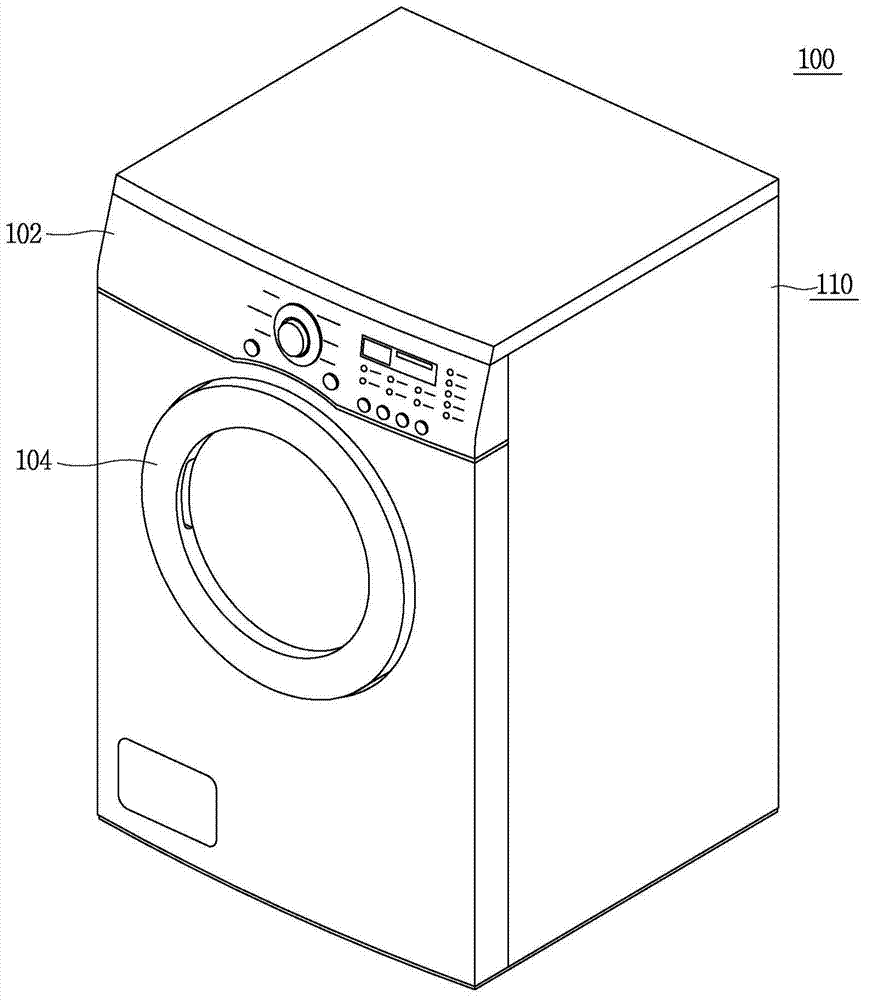
[0040] figure 1 Showing an example clothes dryer, figure 2 showing the internal structure of the clothes dryer of this example, image 3 It is an exploded perspective view showing the internal structure of the clothes dryer of this example. refer to Figure 1 to Figure 3 , the clothes dryer 100 may include a cabinet 110 corresponding to a body of the clothes dryer. The cabinet body 110 has a substantially hexahedron shape. An operation panel 102 for controlling functions of the clothes dryer and displaying states is located on an upper side of the front portion, and a door 104 for loading items to be dried is installed at a lower portion of the operation panel 102 .

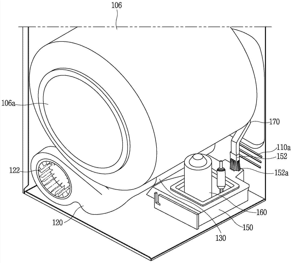
[0041] refer to figure 2 , the drum 106 is rotatably mounted to the cabinet 110 , the drum has an inlet 106 a configured to be opened or closed by the door 104 . In addition, a fan case 120 connected to communicate with the inner space of the drum 106 is located at a lower portion of the front surface por...


PUM


Abstract

A dryer with a heat pump that includes a cabinet , a drum installed within the cabinet, and an exhaust duct configured to exhaust air from the drum to outside of the cabinet . The dryer also includes a fan configured to inhale air from the drum and pump the air to the exhaust duct, an evaporator configured to exchange heat with air being exhausted through the exhaust duct, and a condenser disposed at a rear side of the drum. The dryer further includes an intake passage member configured to guide air that has passed through the condenser into the drum and a compressor and an expansion apparatus configured to define a heat pump along the evaporator and condenser.

Description

technical field [0001] The present invention relates to a clothes dryer with a heat pump. Background technique [0002] Generally, a laundry treating device having a drying function, such as a washing machine or a clothes dryer, is a device that receives laundry in a washing-finished state in a drum. The laundry treating device finishes the dehydration process, and supplies hot air into the drum to evaporate moisture of the laundry, thereby drying the laundry. [0003] For example, a clothes dryer may include: a drum rotatably disposed in a cabinet to receive laundry; a driving motor configured to drive the drum; a blower fan configured to blow air into the drum; and a heating device configured to For heating the air entering the drum. In addition, the heating device can utilize high-temperature resistance heat generated by electric resistance or combustion heat generated by combustion gas. [0004] The air discharged from the drum contains the moisture of the laundry, so...

Claims


Application Information

Patent Timeline
Patent Type & Authority Applications(China)
IPC IPC(8): D06F58/02D06F58/20
CPCD06F58/20D06F58/206D06F58/02D06F58/04
Inventor 郑暎锡李东根金明锺
Owner LG ELECTRONICS INC
Why Eureka
Try Eureka