

Microcomputer controlled liquid heating device
A heating device and microcomputer technology, applied in the direction of fluid heaters, coupling devices, water heaters, etc., can solve the problems of potential safety hazards, contact points, mold manufacturing costs, etc., to achieve ingenious design, excellent performance, and reduced structure troublesome effect of design
Inactive Publication Date: 2010-12-01
MIDEA GRP CO LTD
View PDF1 Cites 0 Cited by
- Summary
- Abstract
- Description
- Claims
- Application Information
AI Technical Summary
Problems solved by technology
Of course, the purpose of all this is because the mains AC electrodes used in this device are directly connected to the connectors, however, what the inventors did not consider is that even if this is done, there are still potential safety hazards
In addition, because such a connector is set in the device, it will cause inconvenience in mold design or structural design, and even expensive mold manufacturing costs
In addition, although the safety standard requires that the groove width of the connector must be less than or equal to 3mm, these contacts may still be touched
Method used
View moreImage
Smart ImageViewing Examples

Examples
Embodiment 1
Embodiment 2
Embodiment 3
Login to View More PUM
 Abstract
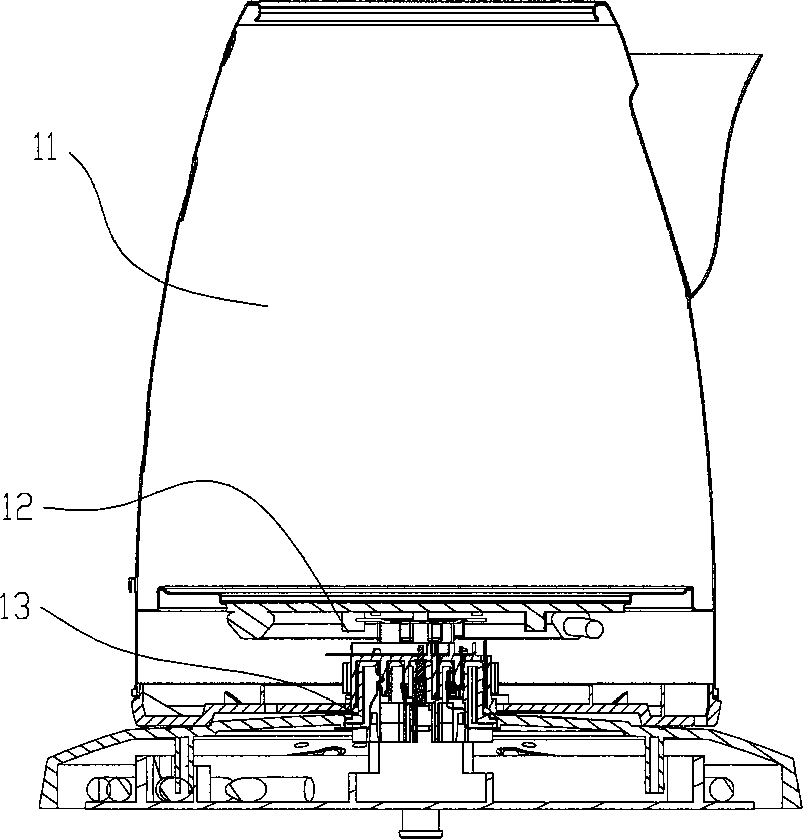
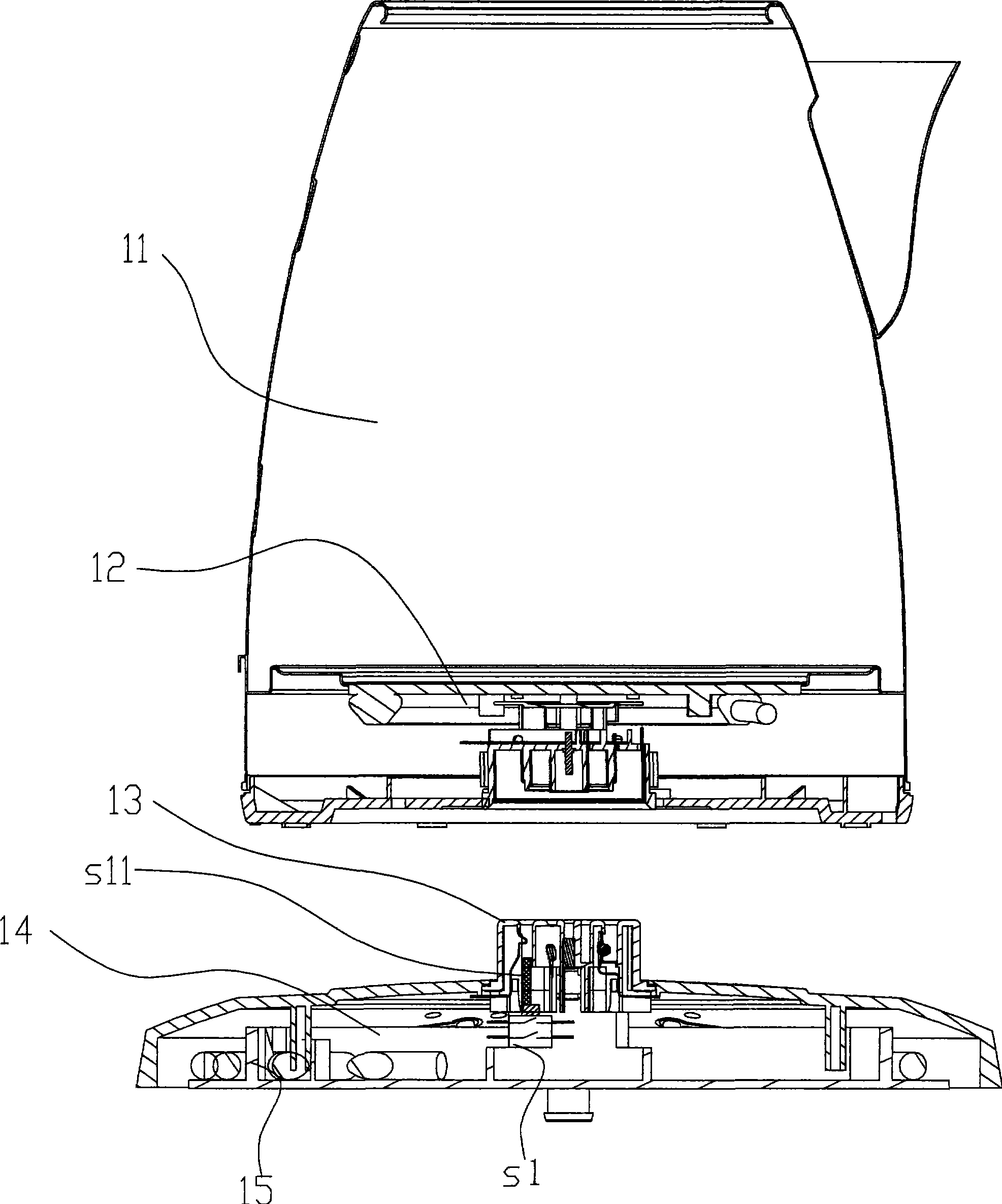
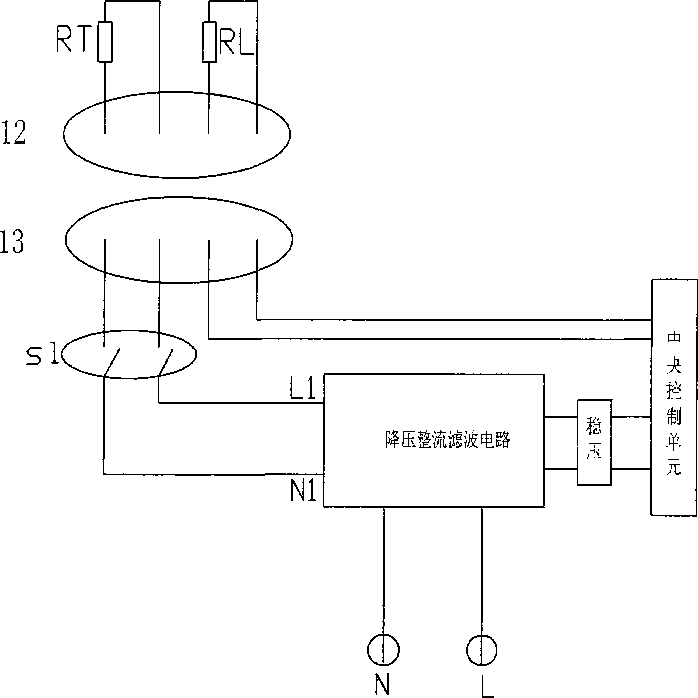
The invention relates to a micro-computer liquid heating device, such as electric kettle and coffee pot. The invention consists of heating container unit, bed unit and connector. The connector includes the upper part and lower part fixed with conduction pole for delivering electric signal. The upper part of connection is fixed on the hating container unit to make up main part. The lower part of connection is fixed on the bed unit to make up bed part. The main part and bed part implement random connection and detachment through the upper part and the lower part of connecter. The bed part has physics on-off or electric on-off for control the current when the main part and bed part detaches. Because when the main part and the bed part detaches and there is no electric current outputting fromexchange pole of naked connecter, it can assure the safety of user and decrease unnecessary structure design trouble. And also the requirement f wireless connector become very broad, so the pole chipcan be fixed connector at random.
Description
Microcomputer liquid heating device Technical field: The invention relates to a microcomputer liquid heating device, in particular to a microcomputer liquid heating device such as an electric kettle, a coffee pot, etc., and belongs to the transformation technology of a microcomputer liquid heating device. Background technique: Currently commercially available liquid heating devices, such as electric kettles, coffee pots, etc., mostly use mechanical steam induction control devices. Control methods appear powerless. A cordless electric device is disclosed in Chinese Patent No. 00802943.1. In this device, the input power part of the commercial power is directly supplied to the connector during implementation. In this way, when the connector is exposed, the The AC electrode will output AC power, so even if the "groove" of the connector is narrow enough, it still cannot block the very thin needles, which means that there are still considerable safety hazards. Furthermore, the...
Claims
Login to View More Application Information
Patent Timeline
 Patent Type & AuthorityPatents(China)
IPC IPC(8): F24H1/18F24H9/20H01R13/70
Inventor林小艺
OwnerMIDEA GRP CO LTD