Projection device

A projection device and projection technology, applied to projection devices, optics, instruments, etc., can solve the problems of difficult storage, loss, and difficulty in finding the infrared remote control 160, and achieve the effect of convenient storage and not easy loss

Active Publication Date: 2007-11-14
CORETRONIC
View PDF0 Cites 6 Cited by
  • Summary
  • Abstract
  • Description
  • Claims
  • Application Information

AI Technical Summary

Problems solved by technology

[0005] When the projection device 100 needs to be stored after use, since the infrared remote control 160 and the casing 130 are separate components, it is relatively difficult to store.
In addition, users often p

Method used


Image

  • Projection device
  • Projection device
  • Projection device

Examples


Embodiment Construction

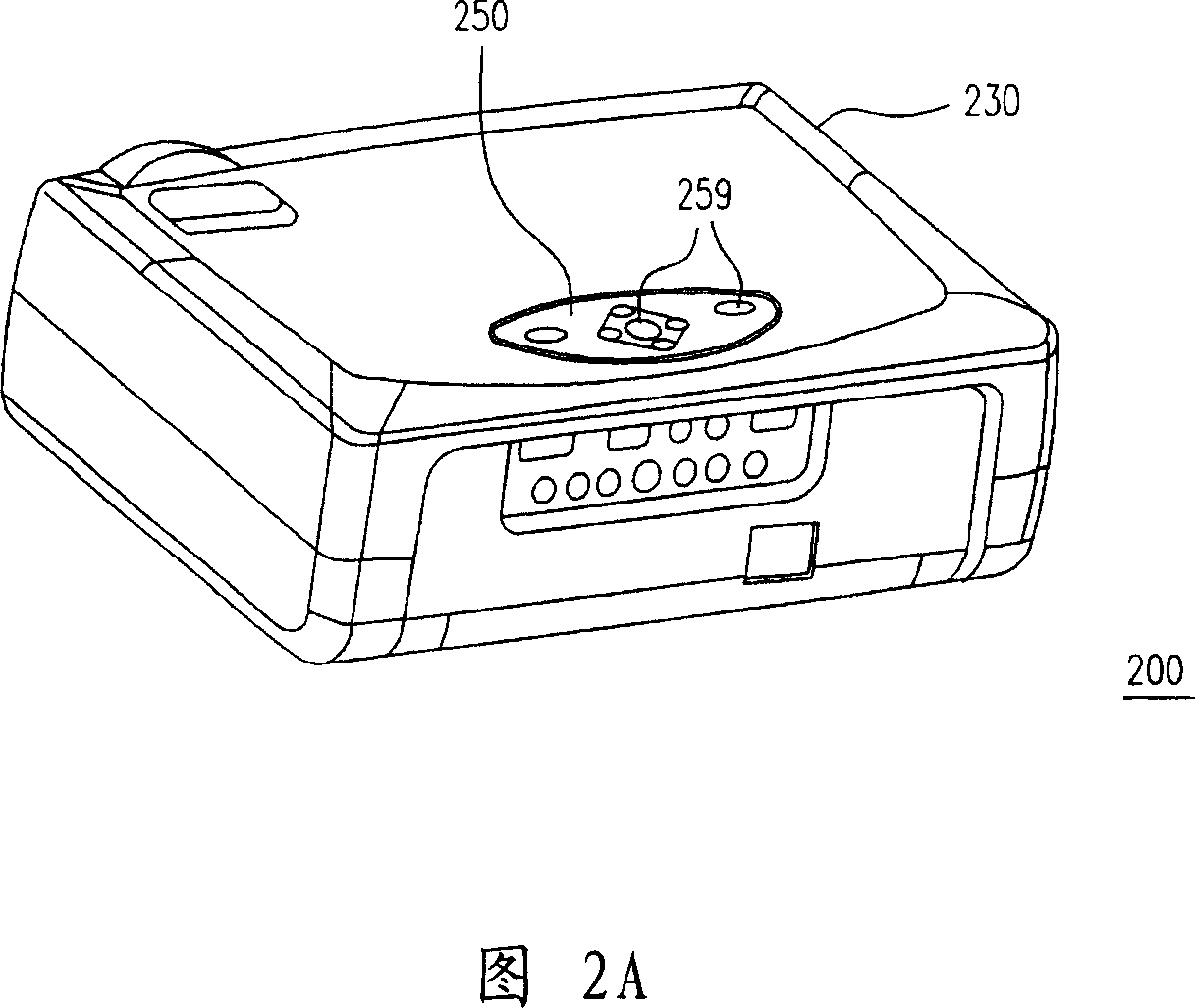
[0044] FIG. 2A is a three-dimensional schematic diagram of a projection device according to an embodiment of the present invention, and FIG. 2B is a structural block diagram of the projection device in FIG. 2A . FIG. 3A is a three-dimensional schematic diagram of the projection device in FIG. 2A in a remote control state, and FIG. 3B is a structural block diagram of the projection device in FIG. 3A . 2A, 2B, 3A, 3B, the projection device 200 of the present invention includes a projection module 210 , a control unit 220 , a casing 230 , a wireless receiving unit 240 and a control panel 250 . The projection module 210 is suitable for projecting images on a screen, and the control unit 220 is electrically connected with the projection module 210 to control the projection module 210 . The casing 230 is suitable for accommodating the projection module 210 and the control unit 220 , and the casing 230 has a card slot 232 exposed outside. The wireless receiving unit 240 is disposed ...


PUM


Abstract

A projection device, including a projection module, a control unit, a cases, a wireless receiver unit and a control panel. Projection module suitable for projection is imaged to the screen, and control unit with the projection module, connectivity to control the projector module. Chassis suited to accommodate projection modules and control modules, and chassis, with exposure to a slot. Wireless receiver modules in the chassis configuration, and control unit with electrical connections, and control panel is removable to place slot in the card. When the control panel is in the exact place, the control panel are the control unit and electrical connections, and provide a suitable control panel signal to the control unit to control the projector module. When the control panel and the exact separation, control panels suitable for providing a wireless signal to a wireless receiver unit to control the projector module.

Description

technical field [0001] The present invention relates to a display device, and in particular to a projection device. Background technique [0002] With the advancement of modern video technology, projection devices have been widely used in occasions such as home theaters and conference reports. In order to increase the operation convenience of the projection device, generally the projection device is equipped with an infrared remote controller, so that the user can remotely control the projection device from a distance. [0003] FIG. 1A is a three-dimensional schematic diagram of a conventional projection device, and FIG. 1B is a structural block diagram of the projection device in FIG. 1A . Please refer to FIG. 1A and FIG. 1B , a conventional projection device 100 includes a projection module 110 , a control unit 120 , a housing 130 , a control panel 140 , an infrared receiving unit 150 and an infrared remote controller 160 . The projection module 110 is used to project im...

Claims


Application Information

Patent Timeline
IPC IPC(8): G03B21/00
Inventor 谢境峰张汎杰刘义铭
Owner CORETRONIC
Why Eureka
Try Eureka