Shadow drawing method and device

A shadow drawing and shadow technology, applied in the field of image processing, can solve the problems of ineffective drawing of shadow maps, limited resolution, squares and jagged edges of shadows, etc.

Active Publication Date: 2007-11-14
TENCENT TECH (SHENZHEN) CO LTD
View PDF0 Cites 7 Cited by
  • Summary
  • Abstract
  • Description
  • Claims
  • Application Information

AI Technical Summary

Problems solved by technology

Therefore, using the ShadowMaps method to generate shadows cannot effectively draw the shadow map in the real lighting scene
[0016] In addition, the sh

Method used


Image

  • Shadow drawing method and device
  • Shadow drawing method and device
  • Shadow drawing method and device

Examples


Embodiment Construction

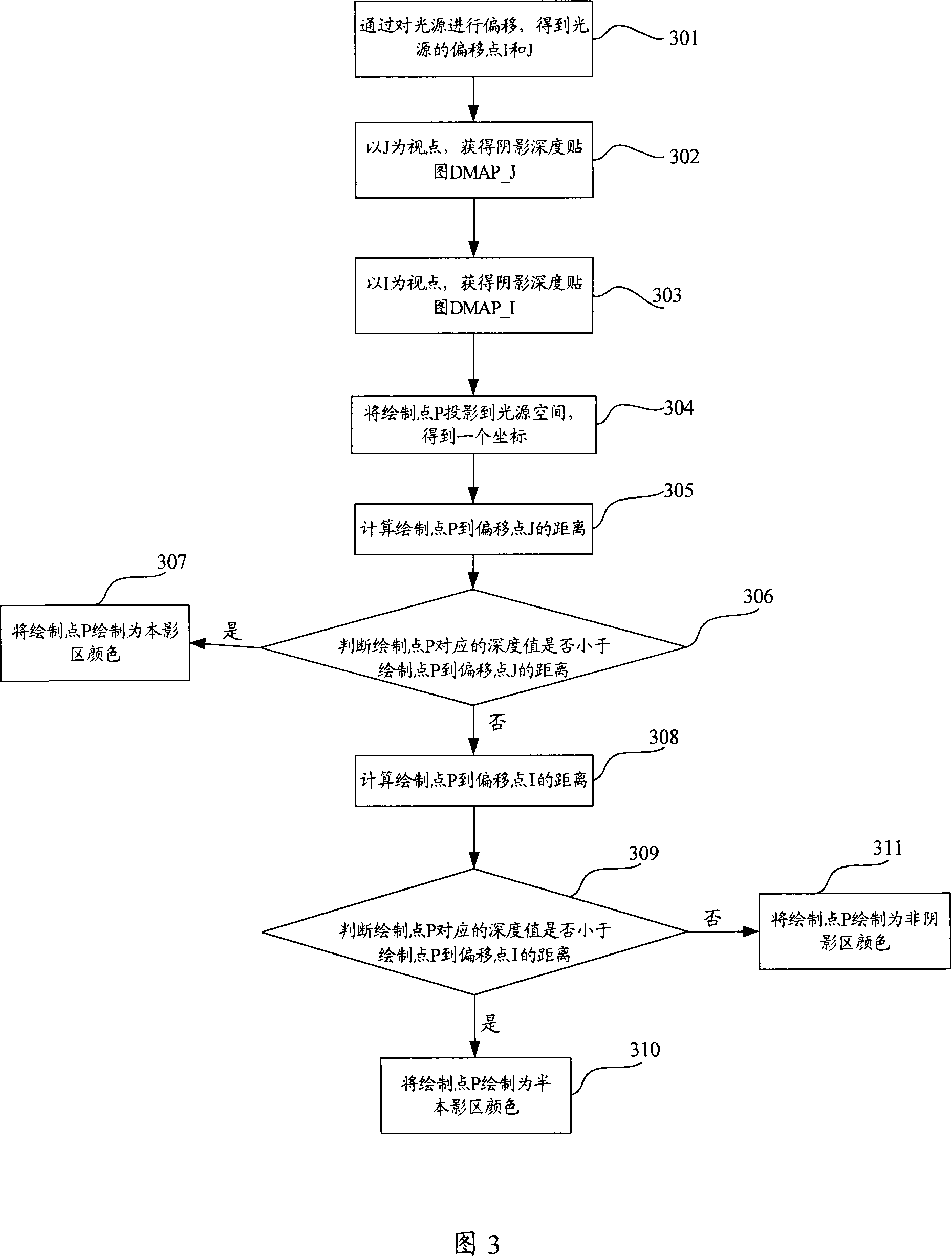
[0091] Embodiments of the present invention provide a shadow drawing method and device, so as to simulate a real lighting effect and draw a shadow map of a scene.

[0092] The embodiments of the present invention will be described in detail below with reference to the accompanying drawings and specific embodiments.

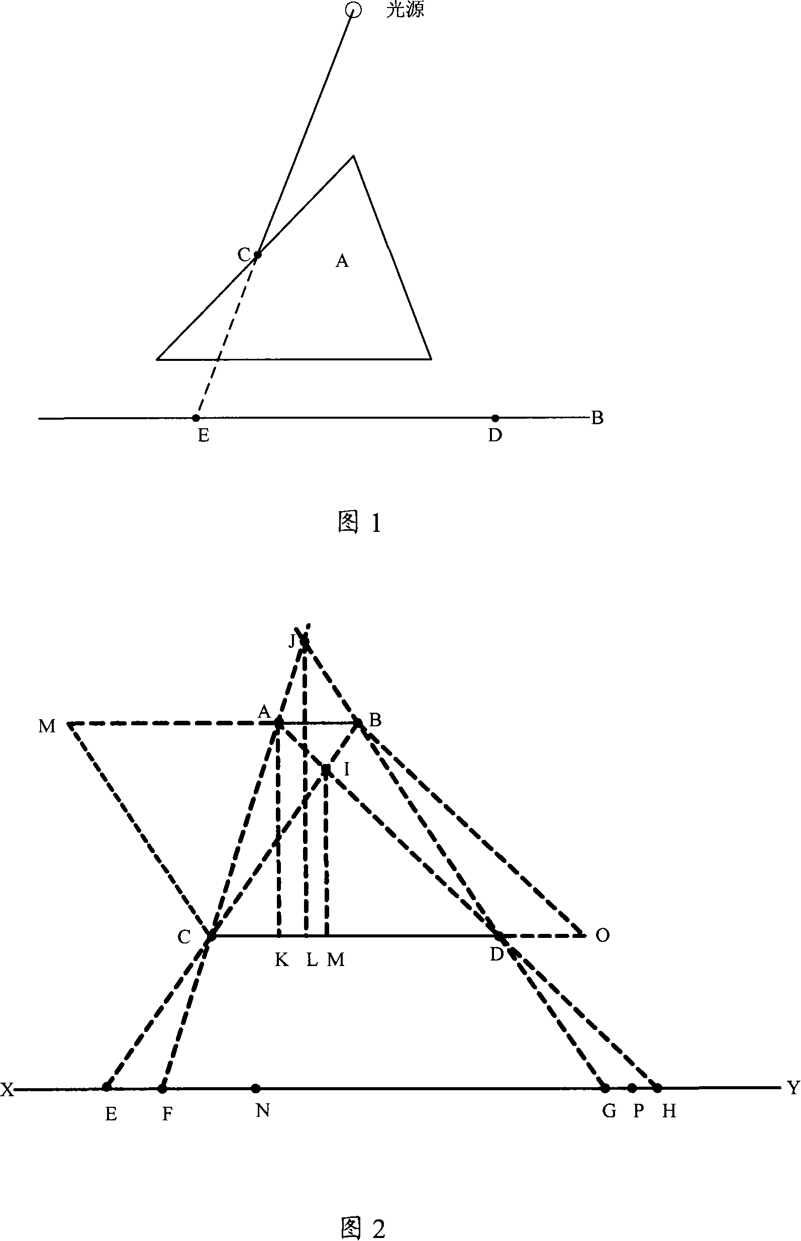
[0093] A real light source is an object with a size. FIG. 2 shows the scene used in the embodiment of the present invention, including: light source offset point I, light source offset point J, object CD (an object that produces shadows), and object XY.

[0094] Wherein, the light source AB is a real light source with a certain size that needs to be simulated, and the light source AB is not included in the lighting scene in the embodiment of the present invention.

[0095] Without considering light diffraction, when the light irradiated by the left point A of the light source AB reaches the object CD, the projection point of the left point C of the object CD on th...


PUM


Abstract

This invention discloses a shadow rendering methods, including: a shift of the light source, offset by the first light source and the second shift points to the first and second shift migration point for point light source location, access scenes of the first and second shadow depth map shadows depth map; drawing points of the first points to the distance between the first shift values from the first shadow depth map, the access point corresponding to the first mapping the depth value; if judged by the depth of greater than or equal to the drawing points of the first migration from the point value, the calculation of the first drawing point to the second migration from the point of value, otherwise referred to drawing point for the first mapping of color from the second shadow depth map, the access point corresponding mapping the depth values; if judged by the depth value is less than the first drawing point to the second shift at the distance, then the drawing for the second point above drawing color value. The present invention also discloses a shadow rendering device to achieve a virtual reality scene illumination, rendering shadow zone.

Description

technical field [0001] The present invention relates to the field of image processing, in particular to a shadow drawing method and device. Background technique [0002] In a real lighting scene, if light encounters an opaque object during propagation, it cannot move forward, and a shadow is formed behind the object, and the shape of the shadow is the same as the outline of the object. [0003] When using a computer to draw a 2D or 3D scene, in order to increase the three-dimensionality and layering of the scene and enrich the performance of the scene, it is necessary to simulate the real lighting effect and draw the shadows in the 2D or 3D scene. [0004] Existing shadow drawing methods include: shadow map method (Shadow Maps) method and the like. [0005] The process of drawing shadows using the Shadow Maps method is as follows: [0006] Step 1: Take the position of the light source as the viewpoint to obtain the shadow depth map of the scene, and the shadow depth map ca...

Claims


Application Information

Patent Timeline
IPC IPC(8): G06T15/60
Inventor 刘皓
Owner TENCENT TECH (SHENZHEN) CO LTD
Why Eureka
Try Eureka