Projector

A projection device and adjustment device technology, applied in projection devices, installations, televisions, etc., can solve problems such as the inability to implement the optical-mechanical focal length design value, incorrect focal length, and unclear images, so as to improve the quality of projection imaging and improve assembly efficiency , Improving the effect of image quality

Inactive Publication Date: 2007-11-21
CORETRONIC
View PDF0 Cites 3 Cited by
  • Summary
  • Abstract
  • Description
  • Claims
  • Application Information

AI Technical Summary

Problems solved by technology

The optical machine 91 is a precision component, and has a certain focal length design value, but because the optical machine 91 itself is manufactured and assembled, often due to factors such as mechanism tolerance, assembly tolerance, optical tolerance or transportation process, the optical machine 91 The Z-axis position (the projection direction of the projection lens of the optical machine 91) produces a displacement change (that is, it is not on the design value), and then causes the focal length to be incorrect and the image to be unclear.
And although the projection device will have other adjustment mechanisms to adjust the focal length or projection position after the optical machine is assembled, in the prior art, because the optical machine 91 itself is fixed on the base 92 and cannot be adjusted, resulting in The Z-axis projection focal length of the optical machine cannot be adjusted, so that the correct design value of the focal length of the optical machine itself cannot be implemented, which seriously affects the imaging quality of the projection equipment. Therefore, how to improve the design so that the optical machine itself has an adjustment function to ensure It has the precise quality foundation of the correct focal length design value when the projection equipment is assembled, and it is a key direction for the industry to make further efforts in research and development.
[0003] In view of the disadvantages of the above-mentioned projection device that its optical mechanism itself does not have an adjustment function and the fact that its structural design is not ideal, the inventor of this case started to develop and conceive its solution, hoping to develop a more adjustable and convenient operation. Optical and mechanical adjustment structure, in order to serve the public and promote the development of this industry, then after a long time of conception, the present invention came into being

Method used


Image

  • Projector
  • Projector
  • Projector

Examples


Embodiment Construction

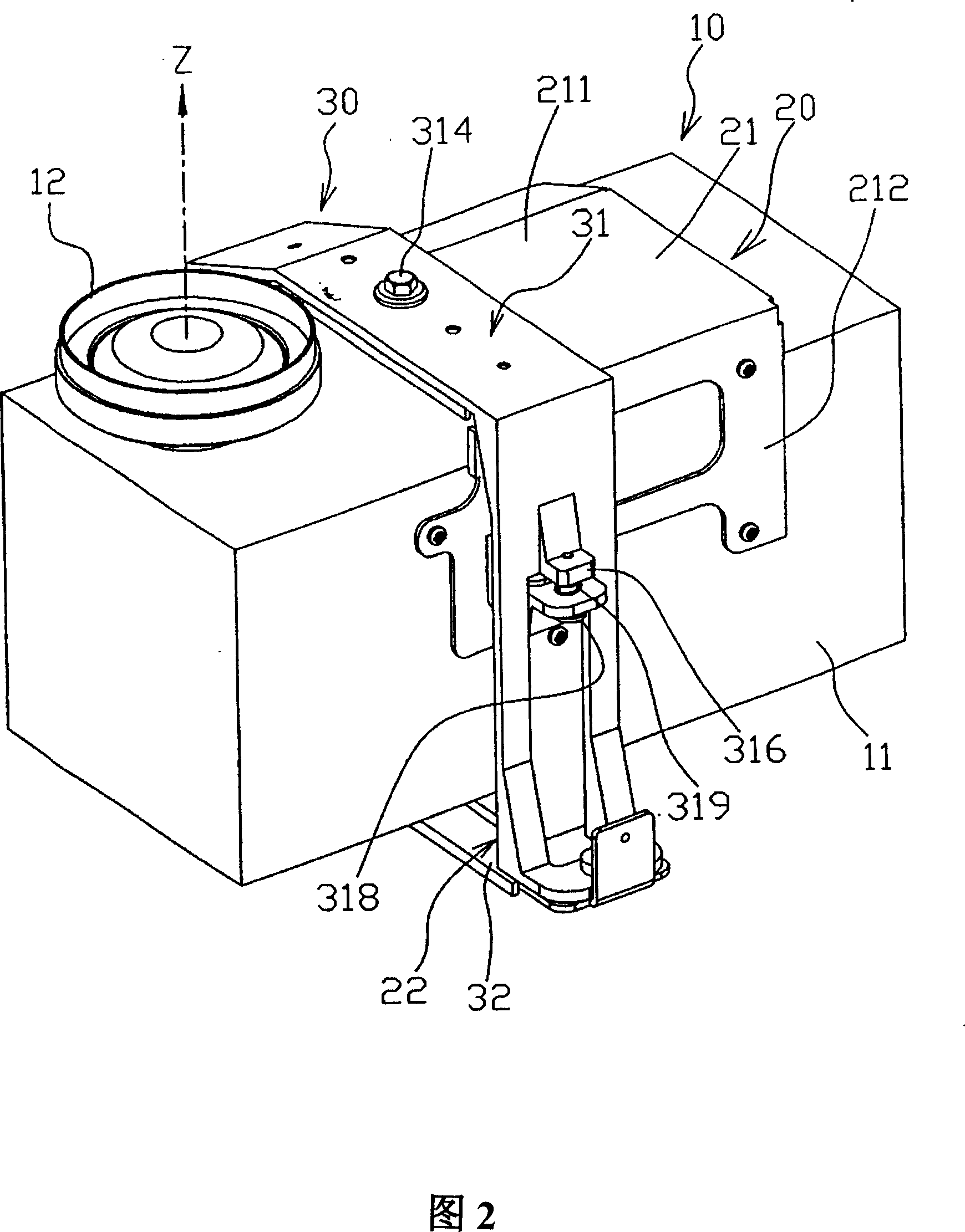
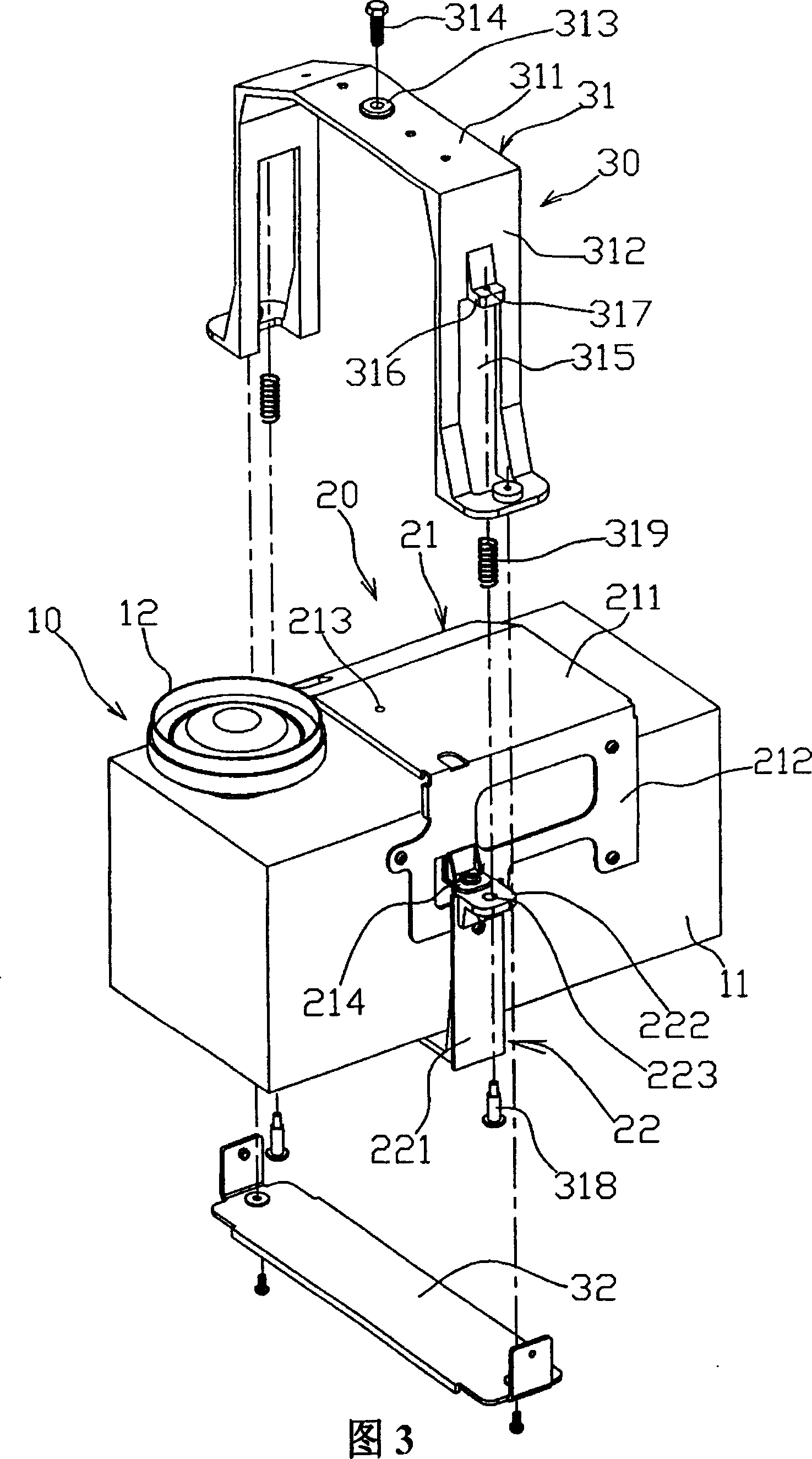
[0016] Please refer to Figures 2, 3, and 4, the projection device of the present invention includes an optical machine device 10 and an adjustment device 30; the optical machine device 10 includes an optical machine 11 and an optical machine fixing assembly 20, the optical machine 11 is provided in front of There is a projection lens 12, the projection direction of the projection lens 12 is defined as the Z-axis direction, the reference direction for focus adjustment, the optical-mechanical fixing assembly 20 includes an optical-mechanical fixing frame 21 and an optical-mechanical fixing base 22, the The optical engine fixing frame 21 is fixed or screwed on the optical engine 11, and includes a first fixing surface 211 perpendicular to the Z-axis direction and two second fixing surfaces 212 located on both sides of the first fixing surface 211. The first fixing surface 211 is provided with an inner adjusting screw hole 213. In a preferred implementation, the first fixing surface 2...


PUM


Abstract

A projection device is prepared as setting fixture component of optical machine on optical machine and arranging an internal regulation screw hole on Z axle direction of said fixture component as well as setting a regulation frame on regulation unit and arranging an external regulation screw hole on Z axle direction of regulation frame then using regulation screw to connect said internal and external regulation screw holes for making optical machine have regulation mechanism.

Description

【Technical Field】 [0001] The present invention relates to a projection device, in particular to a projection device that can adjust the optical machine in the projection device, thereby improving the focus error and improving the projection quality. 【Background technique】 [0002] As shown in FIG. 1, the image projection function of the conventional projection device 90 is mainly generated from an internal optical engine 91, which is fixed on a base 92 and then projects the image on a mirror or screen 93 . The optical engine 91 is a precision component and has a certain focal length design value. However, the optical engine 91 is often manufactured and assembled due to factors such as mechanical tolerances, assembly tolerances, optical tolerances, or transportation processes. The Z-axis position (the projection direction of the projection lens of the optical engine 91) produces a displacement change (that is, not at the design value), which in turn causes the focal length to be i...

Claims


Application Information

Patent Timeline
IPC IPC(8): G03B21/14G03B21/00G02B7/00H04N5/74
Inventor 何文卿
Owner CORETRONIC
Why Eureka
Try Eureka