Ventilator flap for a ventilation system in a vehicle cabin

A ventilation system and cab technology, applied in the field of air injection devices, can solve problems such as complicated and unfavorable installation

Inactive Publication Date: 2007-11-28
FAURECIA INTERIEUR IND
View PDF1 Cites 37 Cited by
  • Summary
  • Abstract
  • Description
  • Claims
  • Application Information

AI Technical Summary

Problems solved by technology

In this embodiment, the air flow is reversed at right angles between upstream and downstream air flow, which is aerodynamically and acoustically unfavorable
Furthermore, the installation of the device on the dashboard is complicated, since there exists an axis of rotation which must extend from left to right or from top to bottom relative to the occupants of the vehicle

Method used


Image

  • Ventilator flap for a ventilation system in a vehicle cabin
  • Ventilator flap for a ventilation system in a vehicle cabin
  • Ventilator flap for a ventilation system in a vehicle cabin

Examples


Embodiment Construction

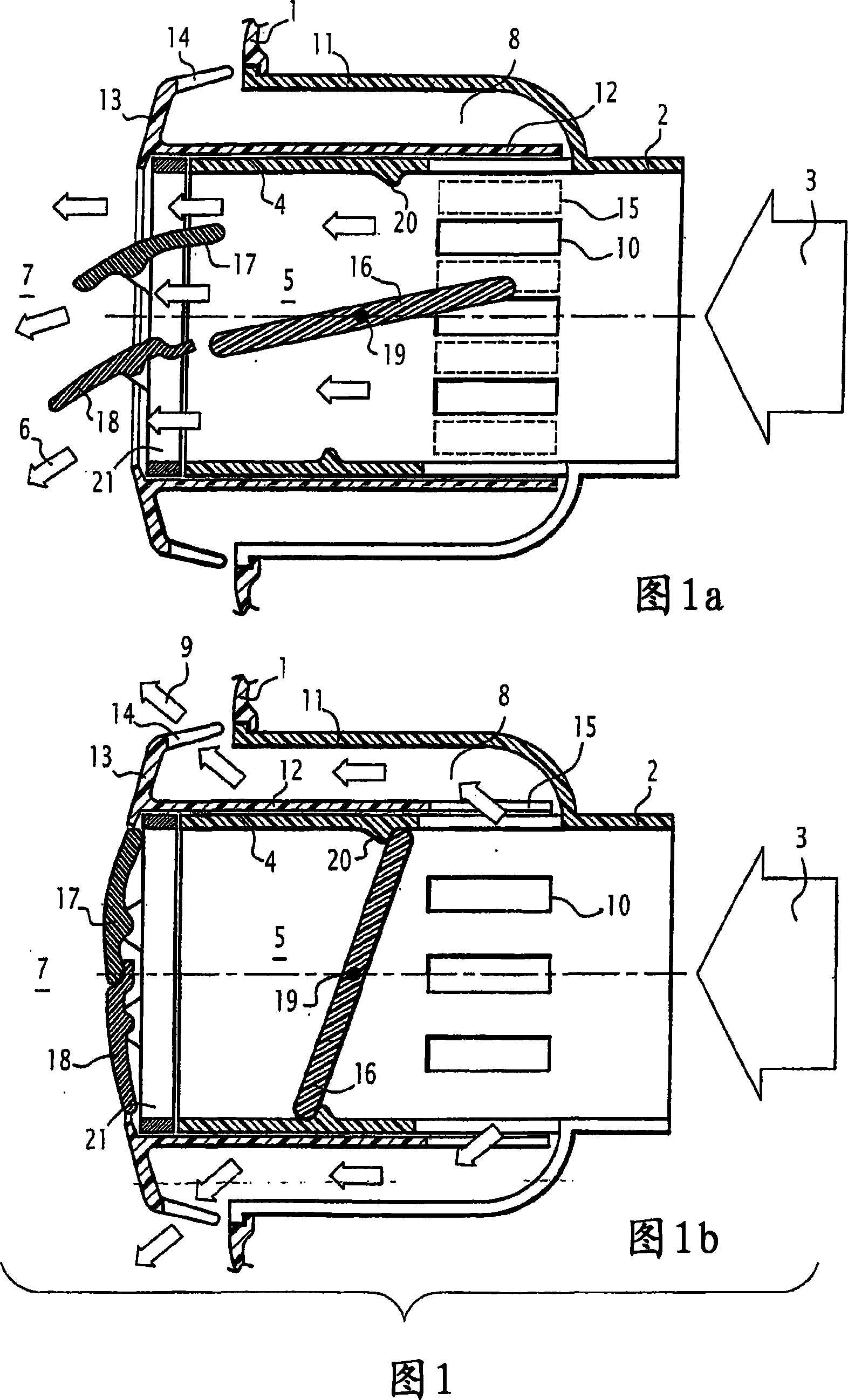
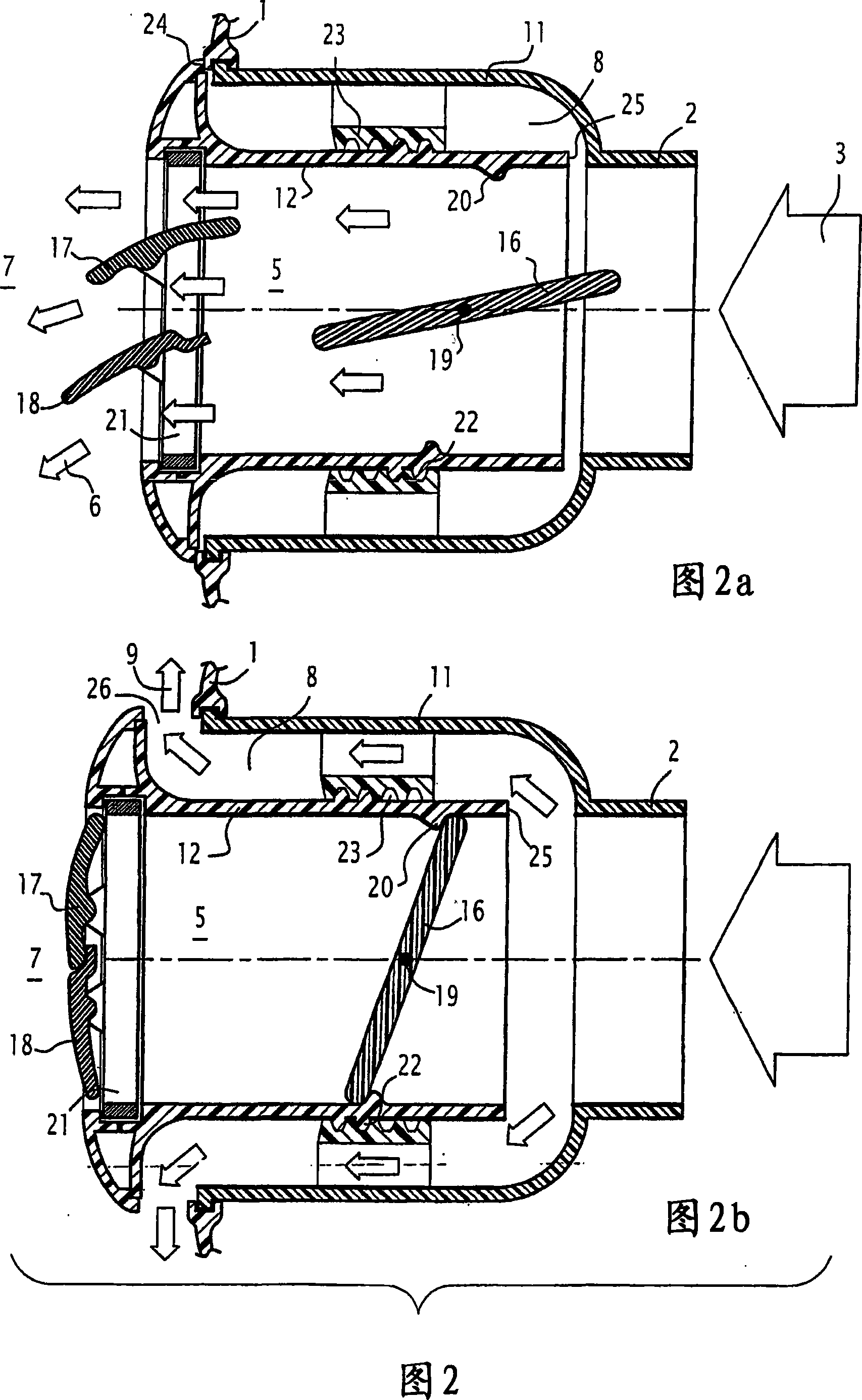
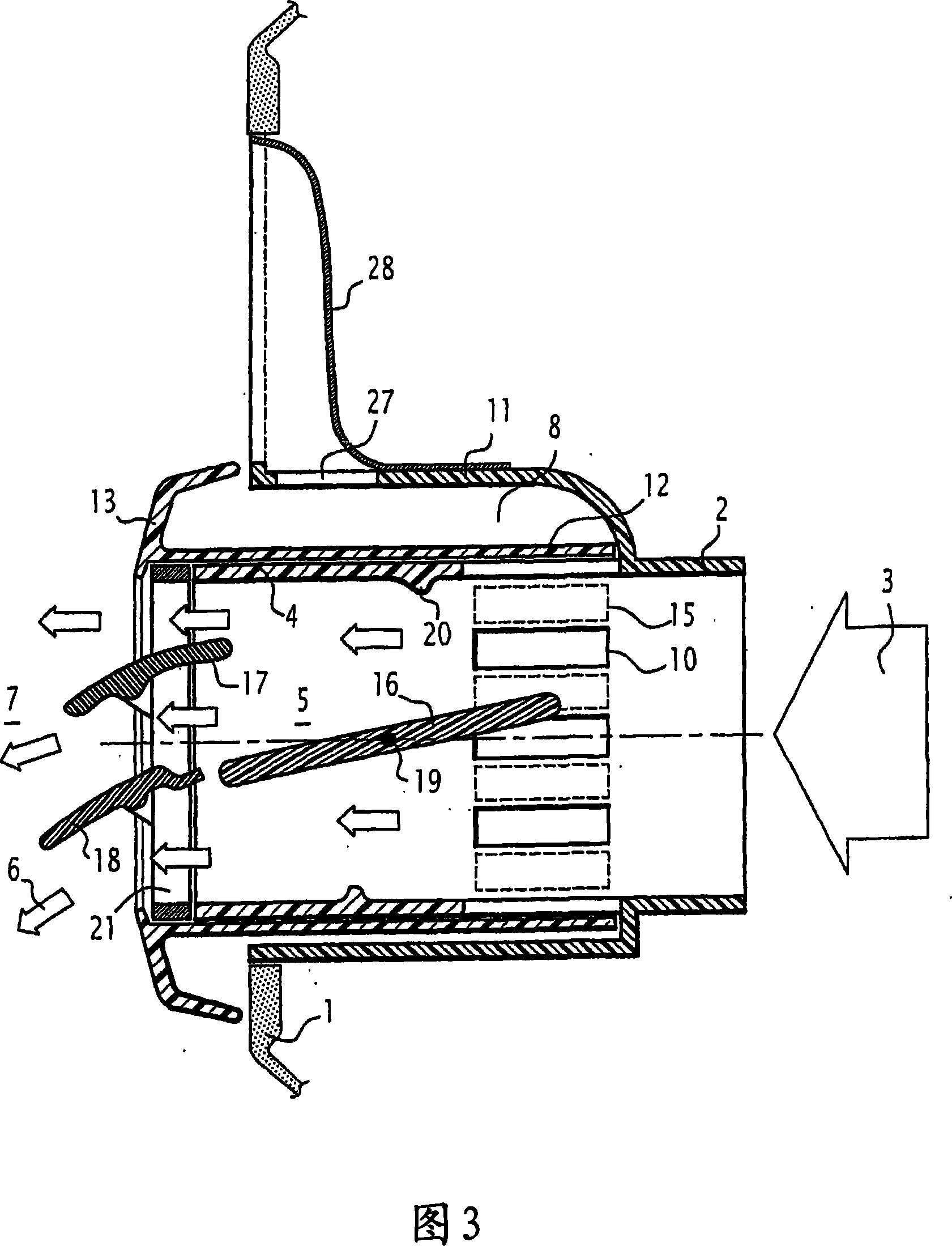
[0021] [20] The first embodiment of the ventilator of the present invention shown in FIG. 1 is intended to be embedded in a hole arranged on the vehicle dashboard 1 and is connected to a main air vent in a connection area 2 via its upstream end. ducts (not shown), the main air ducts themselves are connected to the heating, ventilation and air conditioning equipment of the vehicle. The main air duct supplies air flow upstream of the ventilator, as indicated by arrow 3.

[0022] [21] Downstream of the connection zone 2, the ventilator has two coaxial channels of circular cross-section separated by a cylindrical common wall 4. The central duct 5 is dedicated to the downstream directed airflow (shown by arrow 6 ) into the cabin 7 of the vehicle. The annular duct 8 is dedicated to the entry of downstream diffuse airflow, as shown by arrow 9 .

[0023] [22] The common wall 4 separating the two channels 5 , 8 is provided with spaced holes 10 located in its upstream part and arrange...


PUM


Abstract

The invention relates to a ventilator flap, making up the terminal part of a main air duct providing an upstream air flow (3), said ventilator flap being provided with diffusion means, directing means, and control means for going from one mode to the other which comprises a central duct (5), at least partly coaxial to an annular duct (8), the two ducts (5, 8) having the upstream ends thereof (2) connected to the principal air duct and each having, at the downstream end thereof, one of said diffusion and directing means and a control bush (12), which may be displaced between a first position, in which the above serves to close a connection between the central duct (5) and the annular duct (8) and a second position in which the above serves to open said connection.

Description

technical field [0001] [01] The present invention relates to the automotive industry and, in particular, to an air injection device in the driver's cabin, which forms the terminal part of the heating, ventilation and air conditioning system of the vehicle. Background technique [0002] [02] In the most common configuration of the heating, ventilation and air conditioning system that equips a motor vehicle, there are two types of airflow injected into the cab. The airflow intended to be directed towards the vehicle occupants enters the cabin through directional or steerable ventilators. The airflow for indirect diffusion into the cab enters the cab via a completely different soft-diffusing guide vane of the ventilator. To ensure both direct and indirect diffusion effects, two different types of diffusion elements are used. [0003] [03] In order to simplify the design of the air-diffusing device and to reduce the proportion of the surface of the instrument panel used for th...

Claims


Application Information

Patent Timeline
Patent Type & Authority Applications(China)
IPC IPC(8): B60H1/34
CPCB60H2001/3478B60H1/345
Inventor P·格雷罗
Owner FAURECIA INTERIEUR IND
Why Eureka
Try Eureka