Transparent display board

A transparent board and transparent technology, applied in the direction of instruments, electrical components, circuits, etc., can solve the problems of color spots, dark images, and inability to display moving images on acrylic boards, and achieve the effect of increasing advertising effects.

Inactive Publication Date: 2007-11-28
金圣圭
View PDF0 Cites 13 Cited by
  • Summary
  • Abstract
  • Description
  • Claims
  • Application Information

AI Technical Summary

Problems solved by technology

Although standing signs and banners etc. are commonly used for messaging, they have the disadvantage that they can only display limited content that has been pre-designed; and they require additional electrical lighting to allow this content to be visible at night
However, a disadvantage of conventional electrically illuminated signs is that they are relatively thick because the wires must be routed at the rear and other components must be included therein to achieve a moving image
However, conventional transparent electro-illuminated signs have the disadvantages that: they cannot display moving images; and because the images are relatively dark and have stains on the acrylic, the images cannot be displayed clearly on the acrylic
That is, since the image is displayed by the reflected light of the light source, the displayed image is very dark
Also, since the amount of light received by the acrylic sheet varies depending on the distance between it and the light source, color spots appear on the acrylic sheet

Method used


Image

  • Transparent display board
  • Transparent display board
  • Transparent display board

Examples


Embodiment 1

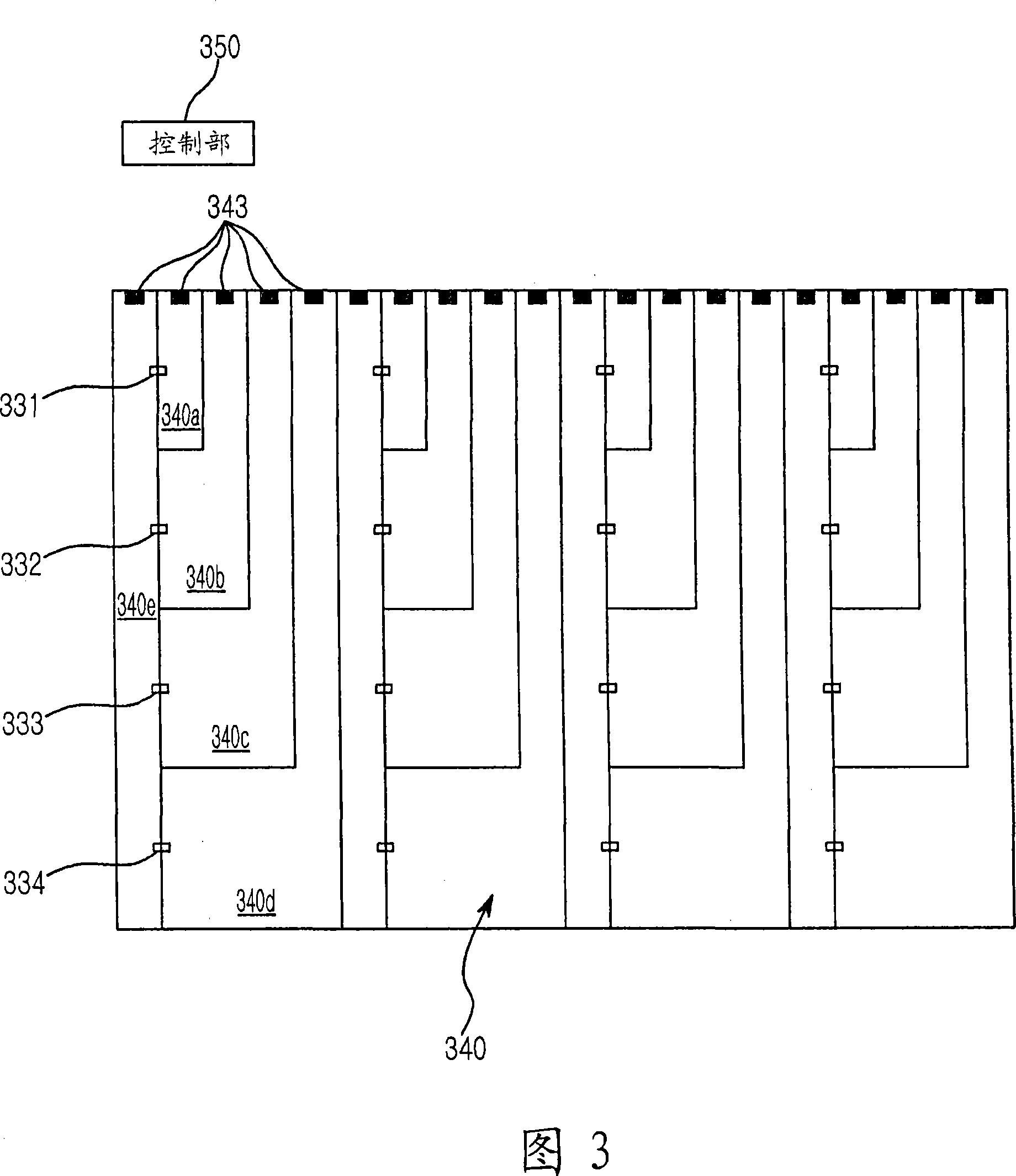
[0038] Referring to FIG. 3, a transparent electrically illuminated sign according to a first embodiment of the present invention includes a plurality of LEDs 331, 332, 333, and 334, each of which has two electrical leads and emits monochromatic light. The transparent electrode 340 is divided into a cathode plate 340e and an anode plate 340a, 340b, 340c, and 340d, a cathode power terminal is formed on one end of the cathode plate 340e, and a cathode power terminal is formed on each end of the anode plate 340a, 340b, 340c, and 340d. Both are formed with an anode power supply terminal. That is, the cathode power supply terminal and the anode power supply terminal are disposed on the same side of the transparent electrode 340 . More specifically, the transparent electrode 340 is divided into: the cathode plate 340e is arranged on the left side of the transparent electrode 340 with respect to FIG. Both the cathode power supply terminal and the anode power supply terminal are arran...

Embodiment 2

[0043] Referring to FIG. 4, a transparent electrically illuminated sign according to a second embodiment of the present invention includes a plurality of LEDs 431, 432, 433, and 434, each of which has two electrical leads and emits monochromatic light. The transparent electrode 440 is divided into a cathode plate 440e having a cathode power supply terminal formed at one end thereof, and anode plates 440a, 440b, 440c, and 440d, and anode plates 440a, 440b, 440c, and 440d in which a cathode plate 440a is connected to the anode plate 440a. , 440b, 440c, and 440d corresponding anode power supply terminals are divided and arranged at both ends of the transparent electrode 440 to face each other. More specifically, the transparent electrode 440 is divided such that the cathode plate 440e is arranged on the left side of the transparent electrode 440 with respect to FIG. . Anode power supply terminals may be formed at both ends of the transparent electrode 440 (at the upper side and ...

Embodiment 3

[0048] Referring to FIG. 5, a transparent electrically illuminated signboard according to a third embodiment of the present invention includes a plurality of LEDs 531, 532, 533, and 534, each of which has four electrical leads and emits different colors according to the status of whether the four electrical leads are input with power. Light. Transparent electrode 540 is divided into cathode plate 540m and anode plate 540a, 540b, 540c, 540d, 540e, 540f, 540g, 540h, 540i, 540j, 540k and 540l, wherein, with anode plate 540a, 540b, 540c, 540d, 540e , 540f, 540g, 540h, 540i, 540j, 540k, and 540l corresponding anode power supply terminals are separated and arranged at both ends of the transparent electrode 540 facing each other. More specifically, the transparent electrode 540 is divided such that the cathode plate 540m is arranged on the left side of the transparent electrode 540 with respect to FIG. , 540k and 540l are arranged on the right side of the transparent electrode 540 w...


PUM


Abstract

The present invention relates to a transparent display board. A transparent electrically-illuminated sign is disclosed. The transparent electrically-illuminated sign includes a first transparent board, a second transparent which is installed apart from the first transparent board at a certain distance, facing the first transparent board, a plurality of LEDs, a transparent electrode, a filling material which is transparent and filled between the transparent electrode and the second transparent board, and a controller. The transparent electrode is formed on one of both faces of the first transparent board as the transparent electrode is coated thereon, in which the face coated by the first transparent electrode faces the second transparent board. The transparent electrode forms at least more than one close circuit plate which is divided into a cathode plate and a plurality of anode plates. The cathode plate is connected by each cathode lead of the plurality of LEDs, which are separated from each other by a certain distance. The cathode plate forms a cathode power supply terminal at a certain position thereof to input power from the outside. The anode plates are correspondingly connected by the anode leads of the LEDs, respectively. Each of the anode plates forms an anode power supply terminal at a predetermined position thereof to input power from the outside. The controller is connected to the anode power supply terminals, such that it can control power supplied to the cathode and anode plates to turn on and off the LEDs. Therefore, the transparent electrically-illuminated sign configured to be thin and transparent can display moving images, as each LED is turned on and off, consuming low power.

Description

technical field [0001] The present invention relates to electrically illuminated signs, and more particularly to an electrically illuminated sign capable of displaying moving characters or image. Background technique [0002] Typically, a directional or advertising message can be communicated to the public by some means such as a standing sign or banner on which predesigned characters or images are displayed. While stand-up signs, banners etc. are commonly used for messaging, they have the disadvantage that they are only capable of displaying limited content that has been pre-designed; and they require additional electrical lighting to allow this content to be visible at night. [0003] There is another example of an electrically illuminated sign that can display various colored characters or images on it with its own light source, such as LEDs, or even set moving images on it. However, conventional electrically illuminated signs have a disadvantage in that they are relati...

Claims


Application Information

Patent Timeline
Patent Type & Authority Applications(China)
IPC IPC(8): G09F9/33H01L33/42H01L33/44H01L33/48
CPCG09F9/33G09F13/22G09G3/32Y10S362/80G09F2013/222
Inventor 金圣圭
Owner 金圣圭
Why Eureka
Try Eureka