
Shift-shock reducing apparatus of power train

A technology of power transmission and shift shock, which is applied in transmission control, engine control, machine/engine, etc., and can solve problems such as shift shock

Inactive Publication Date: 2007-12-12
NISSAN MOTOR CO LTD +1
View PDF3 Cites 13 Cited by
  • Summary
  • Abstract
  • Description
  • Claims
  • Application Information

AI Technical Summary

Problems solved by technology

This creates a shift shock with torque pop-downfeeling

Method used


Image

  • Shift-shock reducing apparatus of power train
  • Shift-shock reducing apparatus of power train
  • Shift-shock reducing apparatus of power train

Examples


Embodiment Construction

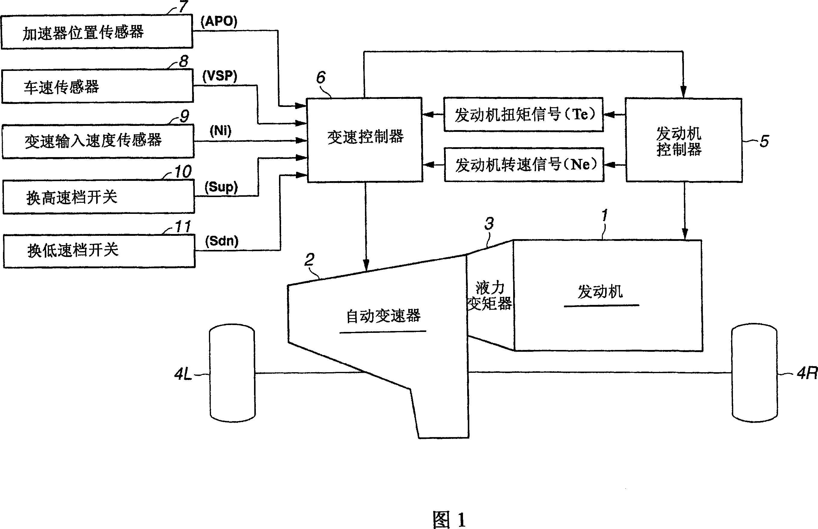
[0034] Referring now to the accompanying drawings, especially to FIG. 1 , the gearshift shock reduction device of the present embodiment is illustrated by taking the power train of a motor vehicle as an example. The power train adopts an engine 1 and an automatic transmission 2 and a differential An automatic transaxle in which gears are combined with each other as a unit. As shown in FIG. 1 , a connecting / disconnecting device 3 is arranged between an engine 1 and an automatic transmission 2 to perform a connecting and disconnecting action between the engine and the transmission. In the illustrated embodiment, a torque converter is used as the connecting / disconnecting device 3 , and a continuously variable transmission abbreviated as "CVT" such as a belt drive CVT or a toroidal CVT is used as the automatic transmission 2 . However, instead of such a CVT, a stepped automatic transmission whose number of speed is limited or limited may also be used. The left front drive wheel 4...


PUM


Abstract

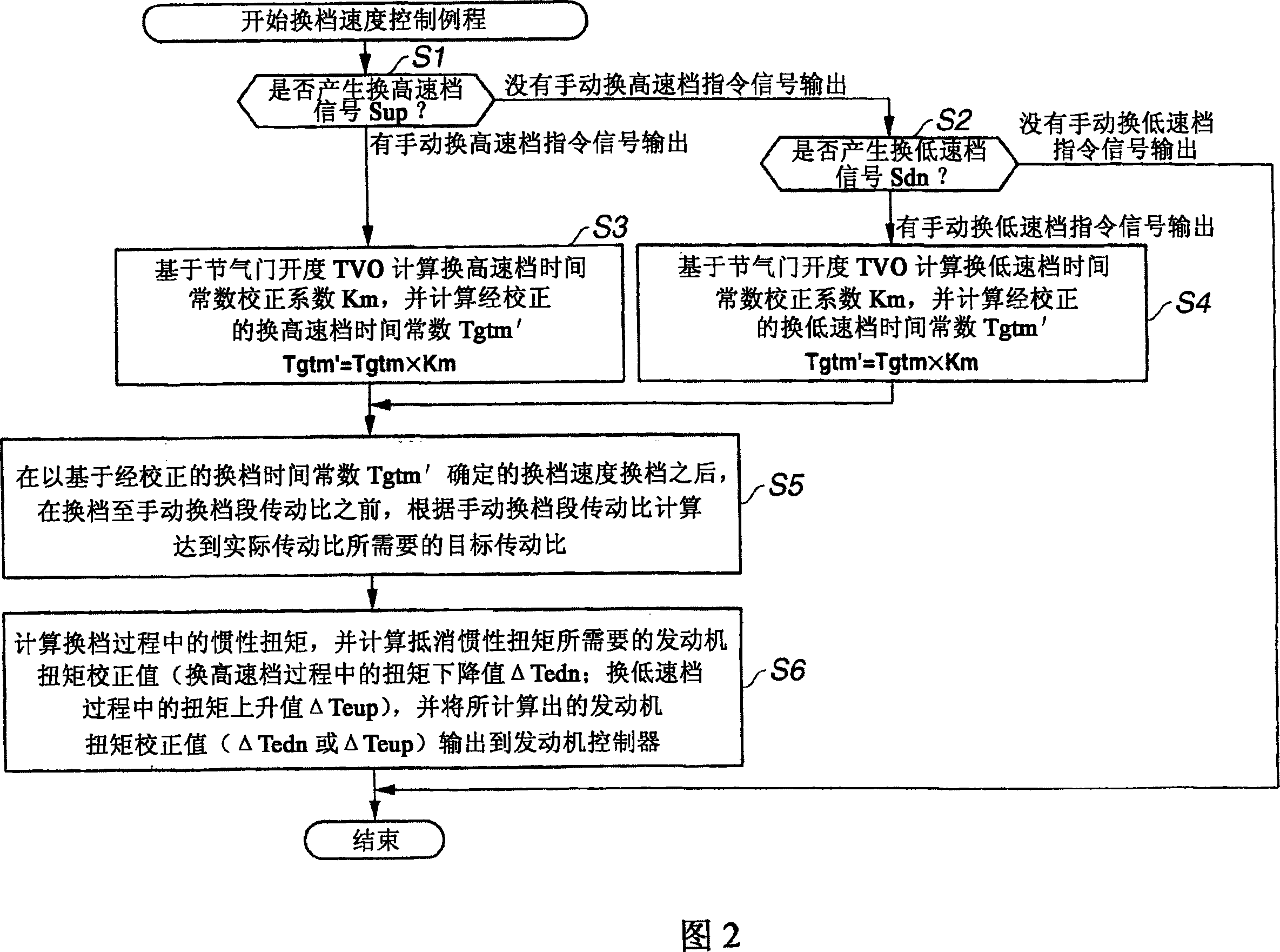
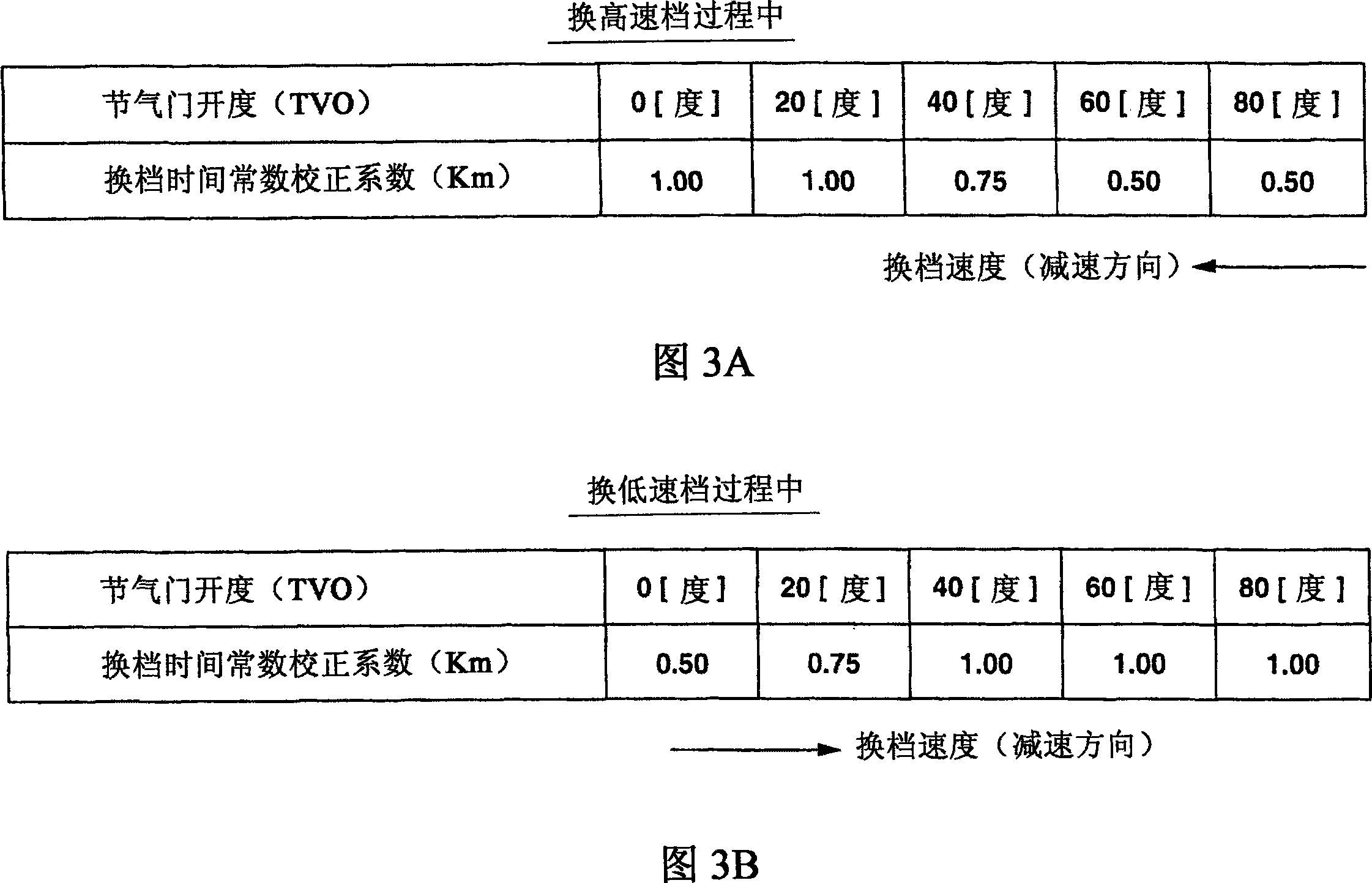
In a shift-shock reducing apparatus of a power train employing an engine (1) and an automatic transmission (2), an engine controller (5) executes engine-torque correction for canceling an inertia torque generated owing to a change in transmission input speed (Ni) during a shift, for shift-shock reduction. A transmission controller (6) includes a shift-speed correction circuit (S3-S4) for compensating for a shift speed of the automatic transmission (2) depending on engine load (TVO), so as to effectively suppress the generated inertia torque, thereby aimfully reducing or suppressing shift shocks.

Description

technical field [0001] The present invention relates to a shifting impact reduction device for a power transmission system using an engine and an automatic transmission, in particular to the improvement of the automatic transmission shifting impact reduction control technology. The shift shock caused by the positive and negative inertia torque generated in the Background technique [0002] During the shifting process of an automatic transmission, changes in the transmission input speed occur due to changes in the transmission ratio. Inertial torque due to shift input speed changes can cause shift shock. [0003] When an automatic transmission is shifted up from a low-side gear ratio to a high-speed side gear ratio, the shift input speed is reduced in accordance with the decrease in the gear ratio. Since the shift input speed decreases, positive inertia torque is generated (in other words, inertia torque is released), and thus the engine torque is increased by an amount cor...

Claims


Application Information

Patent Timeline
IPC IPC(8): F16H61/04F16H59/00F02D29/00F16H59/14F16H59/42F16H61/68F16H63/50
CPCF16H61/686B60W30/20F16H61/0437F16H61/66259F16H2059/147F16H2306/42F16H59/14B60W10/06F16H61/08B60W2510/0695F16H63/502B60W10/11B60W30/19F16H2302/04
Inventor 门野亮路和久田浩司入山正浩大滝绫一木村优典落合辰夫小林淳文若林秀一
Owner NISSAN MOTOR CO LTD
Learn More