Rotary knife with blade bushing

A technology of blades and knives, which can be used in slaughtering accessories, boning shears/bone crushers, metal processing, etc., and can solve problems such as wear and defects at the blade bonding

Inactive Publication Date: 2007-12-19
HANTOVER
View PDF0 Cites 12 Cited by
  • Summary
  • Abstract
  • Description
  • Claims
  • Application Information

AI Technical Summary

Problems solved by technology

Blade misalignment is common, especially when blades are changed frequently, and this misalignment often results in excessive wear on the cutter assembly or blade bond in the knife
For this and other reasons, prior art knives are deficient in allowing rapid and frequent blade changes

Method used


Image

  • Rotary knife with blade bushing
  • Rotary knife with blade bushing
  • Rotary knife with blade bushing

Examples


Embodiment Construction

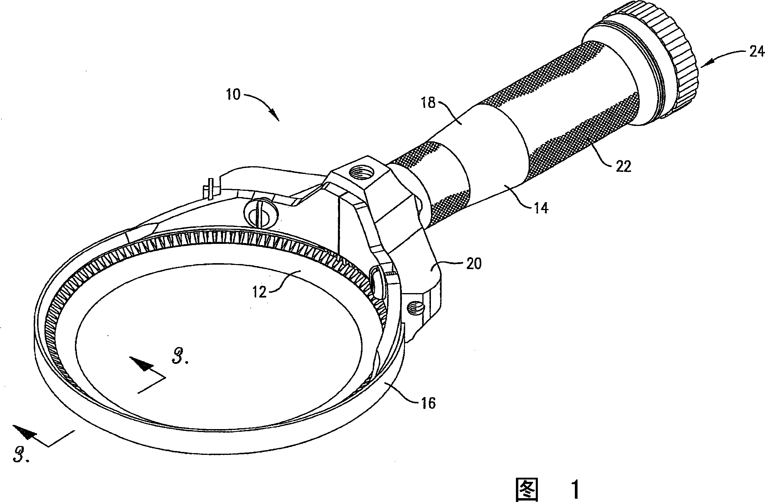
[0016] As shown in FIG. 1, the rotary knife 10 shown therein is particularly suitable for use in handling animal carcasses in an animal slaughterhouse, although other applications of the knife are well within the scope of the present invention. The rotary cutter 10 shown preferably includes an annular rotary blade assembly 12 . The rotary cutter 10 shown is preferably pneumatically driven by a compressed air source (not shown), such as an air compressor. However, the principles of the present invention are equally applicable to rotary knives driven by an alternative external power source, which transmits energy either hydraulically or electrically. The rotary knife 10 generally includes a handle 14 , a blade housing 16 , and a rotary blade assembly 12 .

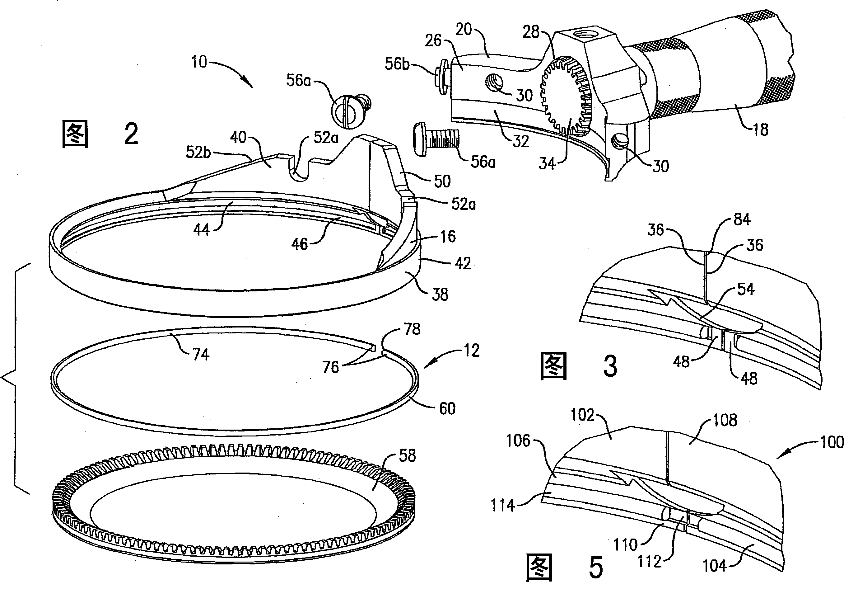
[0017] Referring to FIGS. 1 and 2 , the handle 14 includes a handle housing 18 and a bracket 20 . The handle housing 18 includes a knurled exterior surface 22 for enhancing friction between a user's hand and the handle hous...


PUM


Abstract

A powered rotary knife includes a handle, a blade housing, an annular blade, and a blade bushing for rotatably mounting the blade within the housing. The blade housing includes an inner groove that is operable to receive the blade bushing therein. The blade housing and blade bushing are split in order to expand and receive the blade. The blade includes an outer groove that is also operable to receive the blade bushing. Thus, the blade bushing is spaced between the blade housing and blade and rotatably secures the blade within the blade housing.

Description

technical field [0001] The present invention relates primarily to powered knives, such as those commonly used in meat processing in slaughterhouses. More particularly, the present invention relates to a rotary cutter with a rotating annular blade and an annular bush supporting the blade. Background technique [0002] In the meat processing industry, the use of powered knives for the handling of animal carcasses is well known in the art. The process of carcasses usually involves removing the meat and fat from the various bones and cutting the various bones. Powered tools allow workers to complete the process more efficiently than traditional non-powered tools. In the prior art powered tools are rotary tools with rotating annular blades. Many rotary knives are electrically driven and can rotate the annular blade at very high angular velocities. [0003] Rotary knives are problematic and have limitations. For example, the high speed rotational motion of the ring blades, id...

Claims


Application Information

Patent Timeline
Patent Type & Authority Applications(China)
IPC IPC(8): A22C17/06B26B25/00
CPCA22B5/168A22B5/165B26B25/002
Inventor C·A·里维森
Owner HANTOVER
Why Eureka
Try Eureka