
Rotary engine with improved hybrid features

a hybrid engine and rotary engine technology, applied in the field of hybrid engines, can solve the problems of increasing the charging of batteries and the braking force applied to the drive shaft, and achieve the effects of increasing the braking force of the drive shaft, eliminating and replacing the steering wheel and foot pedal, and increasing the charging of the generator

Inactive Publication Date: 2005-10-13
VASILANTONE MICHAEL M
View PDF10 Cites 37 Cited by
  • Summary
  • Abstract
  • Description
  • Claims
  • Application Information

AI Technical Summary

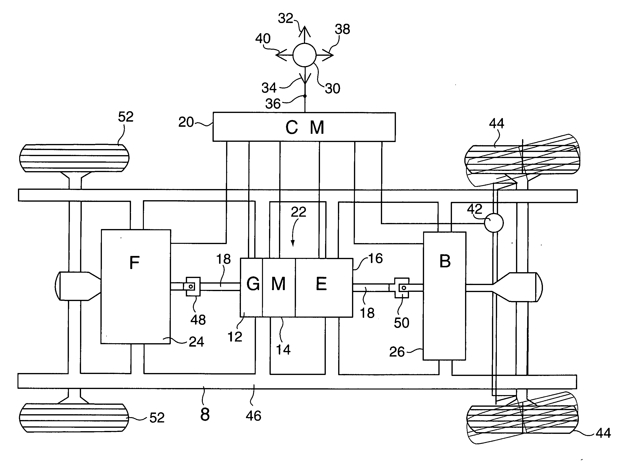
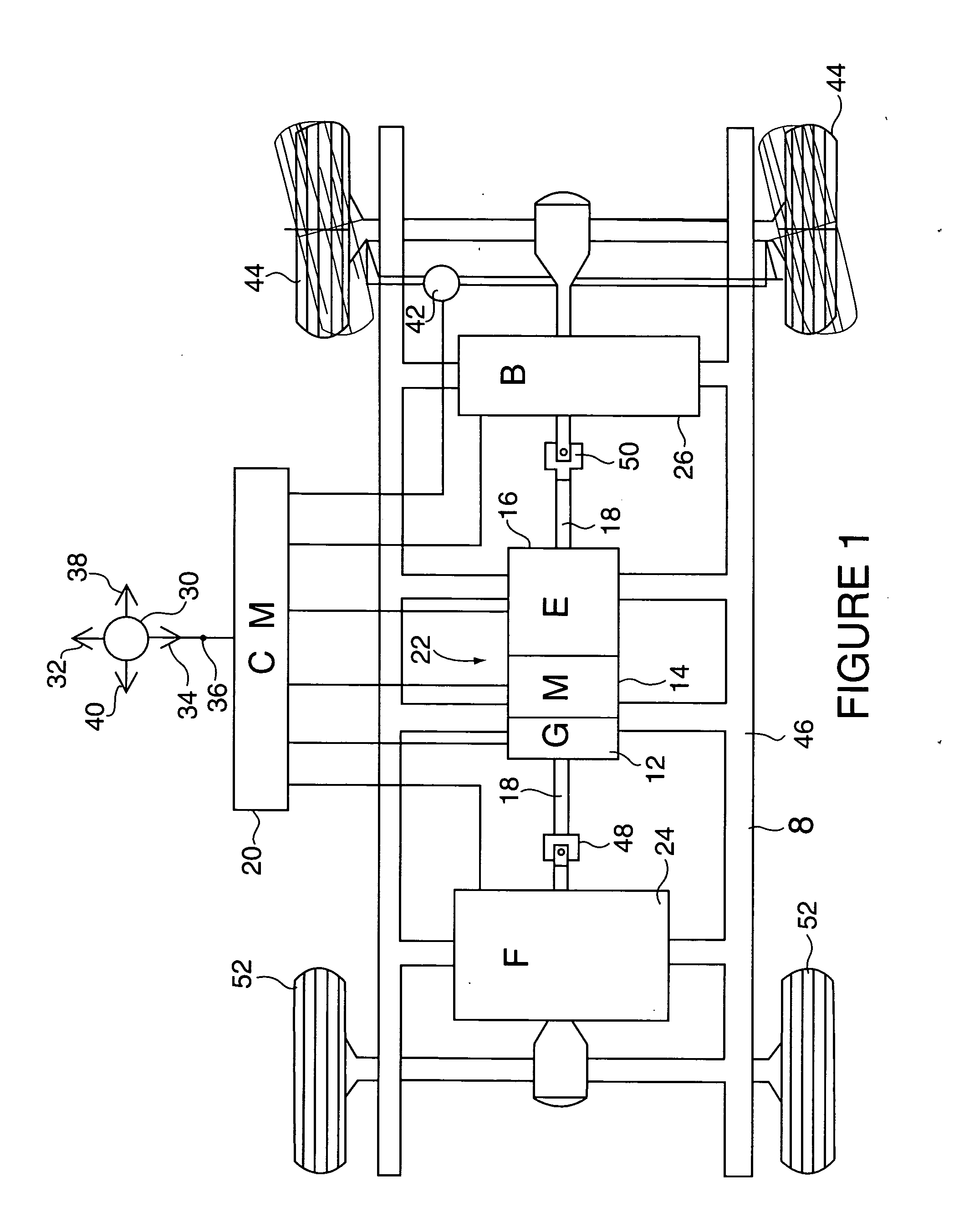
Benefits of technology

[0009] a) My patent, No. 3,971,347 describes a rotary internal combustion engine housing and a concentrically arranged chamber within the housing in receiving an eccentrically disposed cylindrical rotor; the rotor cooperates with the chamber to define a crescent-shaped chamber which is sequentially divided into intake, compression, combustion and exhaust chambers by means of vanes which are pivotally mounted on the annular surface of the rotor and which engage the inner surface of the housing in defining the chamber. The resulting configuration provides efficiency of operation, effective sealing between the rotor and the housing, effective minimalization of heat build up due to frictional contact, and a great rigidity and strength.
[0010] b) My second patent, No. 4,307,695 provides enhanced operation by having a blower and / or superchargers that are driven by the rotary engine. The design includes a rotor, a plurality of pistons angularly mounted in the rotor, an actuator mounted for eccentric rotation relative to the access of rotation of the rotor, a blower, a transverse actuator pin connecting each piston to the actuator, and a plurality of fixed pins connecting the rotor to the actuator. With the fixed pins mounted on the rotor so as to pass through clearance holes in the blower in carrying extension gears which mate with internal gears mounted in the actuator, rotation of the rotor causes rotation of the blower and of the actuator as well. As there set forth, the rotational force that results changes the pressure line in its direction, moving it towards the direction of rotation as the rotational speed increases.
[0012] In accordance with the present invention, the hybrid portion of the rotary engine is modified to include a translator element connected to an electric clutch-brake within the generator component, an operator vertical control lever, and a central programmable control module. As will be seen, these modifications allow for the elimination and replacement of the steering wheel and foot pedals of the conventional vehicle, an increased charging by the generator, and an increased braking of the drive shaft when necessary. The end result will be an increase in fuel efficiency and an increase in operator efficiency.
[0013] With the improvements presented by these modifications, the vehicle operator's primary control element becomes the vertical control lever which provides the entire operator driving function—one by which the lever can be moved in four directions; namely, forward for acceleration, rearward for slow-back and full-back in slowing and stopping respectively, and right and left for steering. Requiring less body movement and enhanced physical and mechanical efficiency than with having to turn a steering wheel or operating a gas or brake pedal, the vertical control lever of the invention may further be easily positioned for right and left-hand, and right and left-side vehicle operation, while providing an enhanced visibility of the dashboard indicators.

Problems solved by technology

In these designs, the generator constantly charges the vehicle's batteries, while increasing revolutions during moments of deceleration increases the charging of the batteries and the braking forces applied to the drive shaft.

Method used


Image

  • Rotary engine with improved hybrid features
  • Rotary engine with improved hybrid features
  • Rotary engine with improved hybrid features

Examples


Embodiment Construction

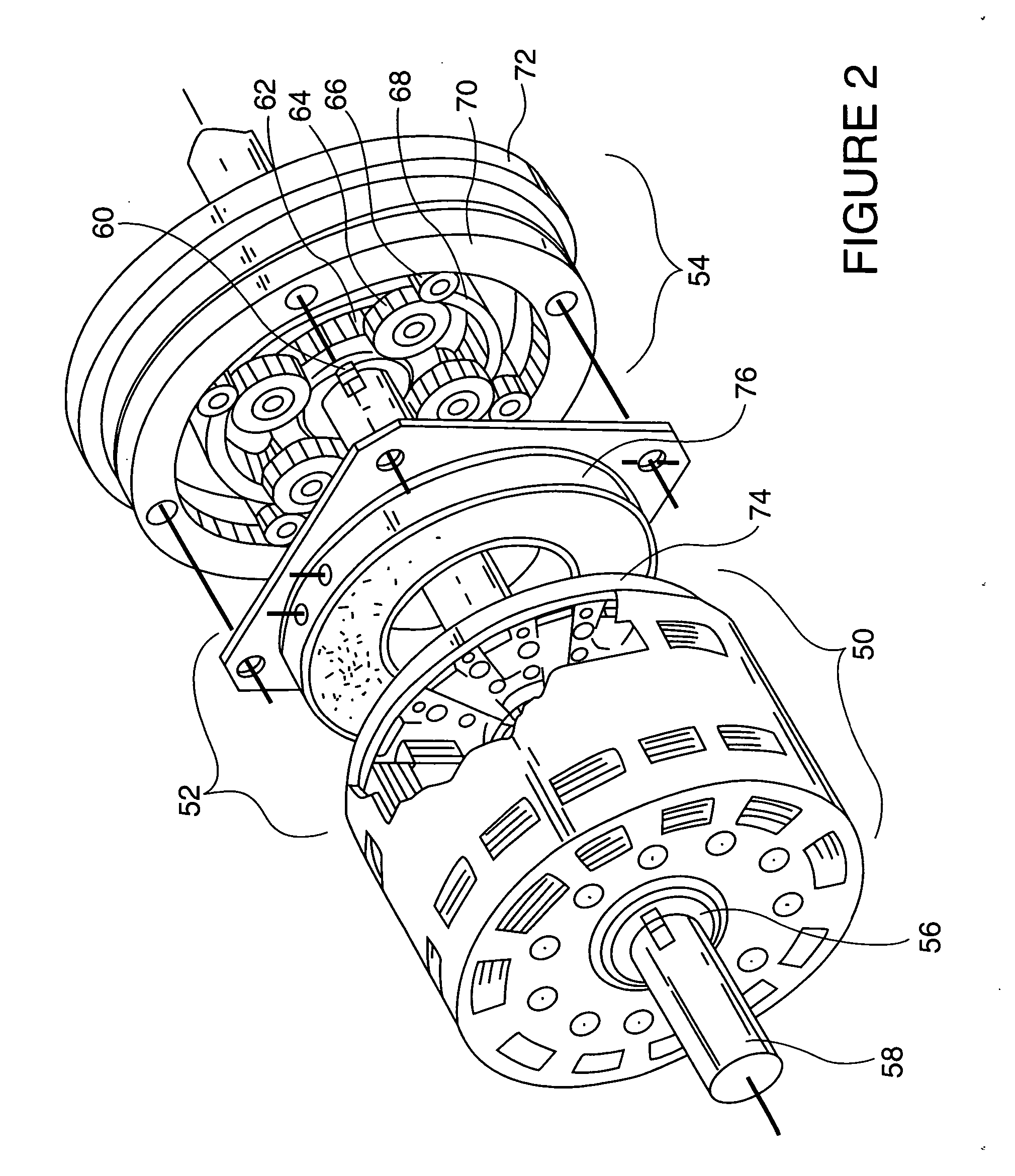
[0017] As with the hybrid engine of my U.S. Pat. No. 6,698,395 invention, the three major components of the hybrid engine here include a gas rotary engine, an electric motor, and an electrical generator forming a uniform cylindrical shape having a common drive shaft which extends through and out each end. Each component will be understood to be mounted on a one-way journal for clockwise rotation along with an electric clutch. Enclosed in a shell casing or block, these components are attached to the vehicle chassis as a power capsule at a position along the traditional drive shaft—one end of which is connected via universals to the rear wheels, and the other end of which is connected to the front wheels. One element of the generator component is the generator itself, with the other being the translator. The electric clutch (as available from Warner Electric Manufacturing, for example) provides both brake and clutch functions for the power capsule as part of the translator within the ...


PUM


Abstract

A hybrid engine including an electric motor, a rotary internal combustion engine, and an electric generator incorporating a clutch and translator unit to drive the generator at a ratio greater than 1:1 during vehicle slowing and at a 1:1 ratio rate at other times in providing increased braking and fuel efficiency—along with a programmable central control module and vertical control lever in effectuating steering and vehicle operation without the use of a steering wheel or foot gas and brake pedals.

Description

CROSS-REFERENCE TO RELATED APPLICATIONS [0001] None STATEMENT REGARDING FEDERALLY SPONSORED RESEARCH OR DEVELOPMENT [0002] Research and development of this invention and Application have not been federally sponsored, and no rights are given under any Federal program. REFERENCE TO A MICROFICHE APPENDIX [0003] Not Applicable BACKGROUND OF THE INVENTION [0004] 1. Field of the Invention [0005] This invention relates to hybrid engines combining electric motors and generators with combustion engines, in general, and to a hybrid engine in which the motor and generator are combined with a rotary internal combustion engine, in particular. [0006] 2. Description of the Related Art [0007] As is well known and understood, automotive manufacturers are either producing or developing automobiles with hybrid engines which combine electrical power with internal combustion engines. In these designs, the generator constantly charges the vehicle's batteries, while increasing revolutions during moments o...

Claims


Application Information

Patent Timeline
Patent Type & Authority Applications(United States)
IPC IPC(8): B60K6/26B60K6/442B60K6/52B60K6/24B60K6/365B60K6/40
CPCB60K6/24B60K6/26B60K6/365B60K6/442B60K6/52B60L50/62Y02T10/6234Y02T10/6265Y02T10/6295Y02T10/7077Y10S903/951Y02T10/6217Y02T10/62Y02T10/70Y02T10/7072
Inventor VASILANTONE, MICHAEL M.
Owner VASILANTONE MICHAEL M
Learn More