Combustion and exhaust heads for fluid turbine engines

a technology of combustion and exhaust head, which is applied in the direction of liquid fuel engines, machines/engines, mechanical equipment, etc., can solve the problems of dissipation of high pressure energy from combustion, large downward force diverted from the piston, and combustion already occurring, so as to reduce the cost of production, and reduce the effect of production cos

Inactive Publication Date: 2004-10-05
1564330 ONTARIO
View PDF7 Cites 36 Cited by
  • Summary
  • Abstract
  • Description
  • Claims
  • Application Information

AI Technical Summary

Benefits of technology

The rotary engine according to the present invention is simpler and more economical to manufacture than conventional rotary engines, and has fewer components. Hence it is lighter in construction and requires less space.

Problems solved by technology

This results in much of the downward force from the piston being diverted from efficient rotary movement to the application of vertical pressure on the crankshaft's main bearings.
At this position, however, combustion has already occurred and, as the volume of space in the cylinder has increased to one half total displacement, much of the high pressure energy from the combustion has been dissipated.

Method used


Image

  • Combustion and exhaust heads for fluid turbine engines
  • Combustion and exhaust heads for fluid turbine engines
  • Combustion and exhaust heads for fluid turbine engines

Examples


Embodiment Construction

In the following description, similar features in the drawings have been given similar reference numerals.

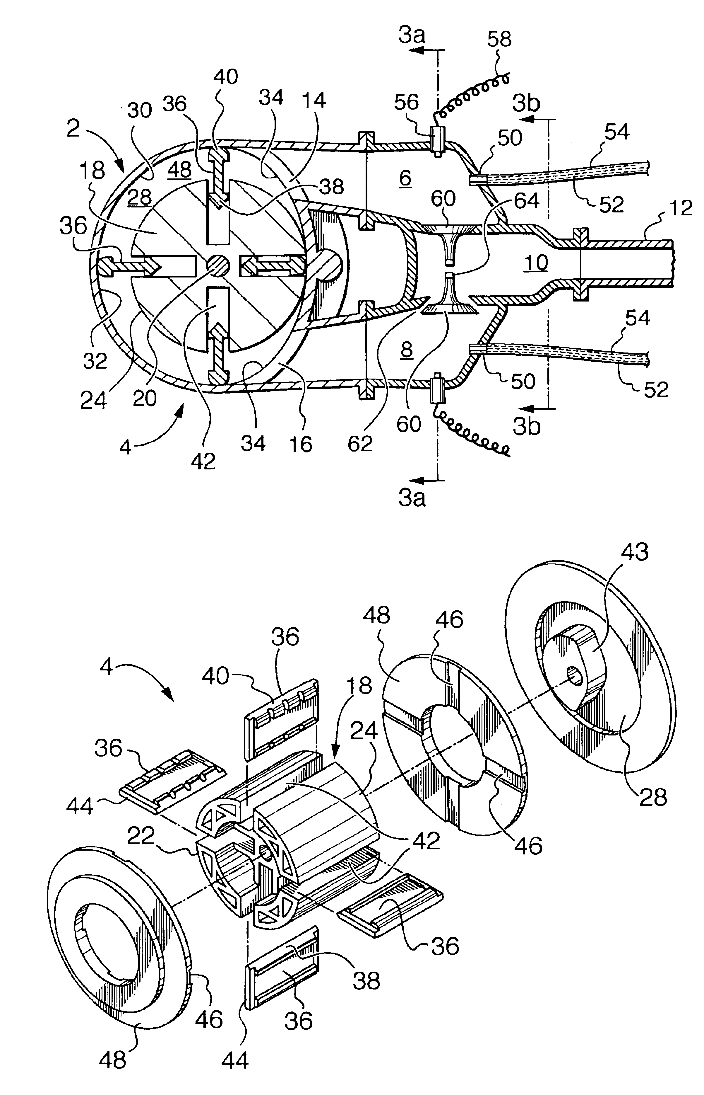
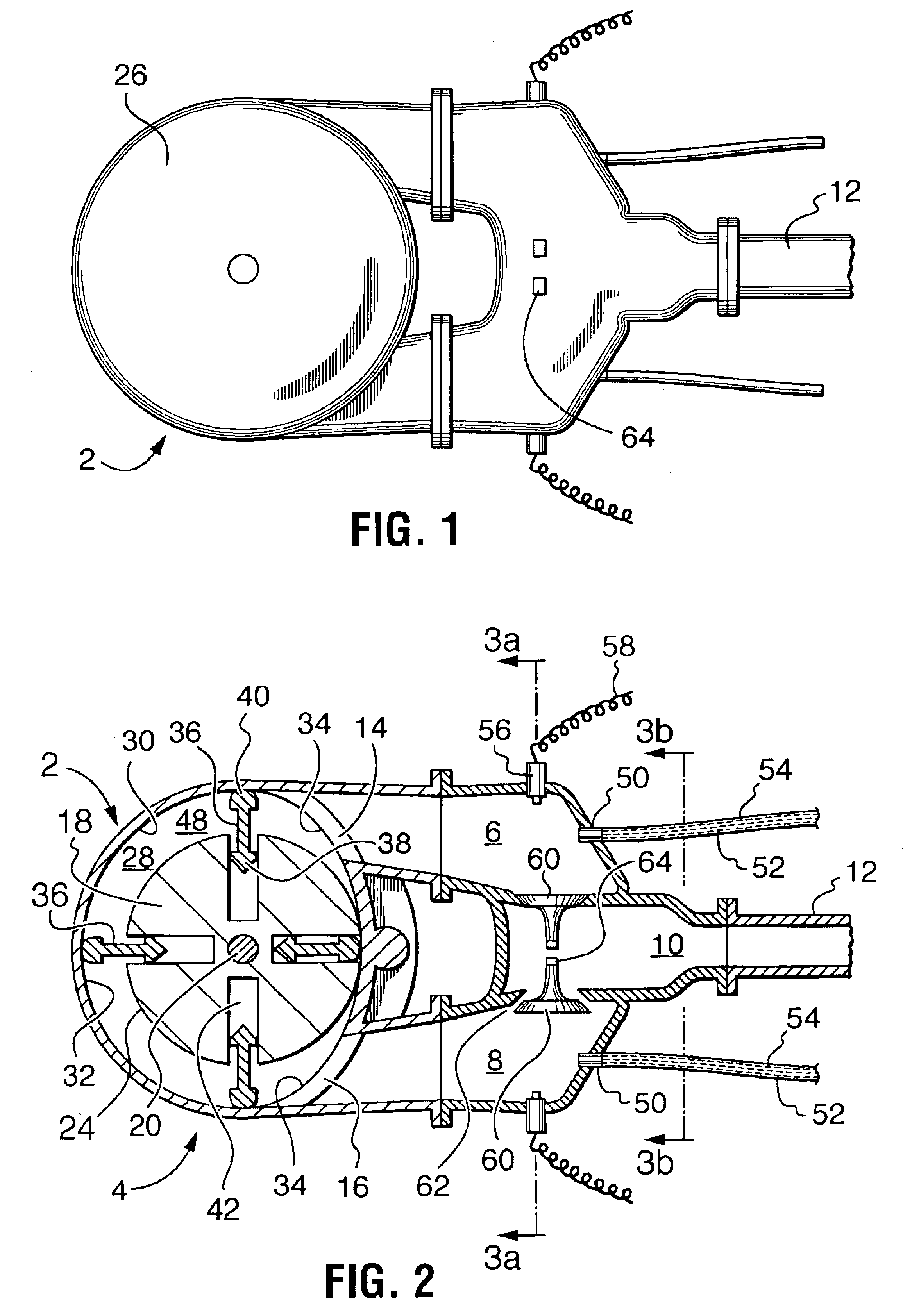
The engine 2 according to the present invention combines a fluid turbine 4 as described and illustrated in applicant's co-pending U.S. patent application Ser. No. 09 / 973,782, with appropriate combustion and exhaust heads as will be described subsequently.

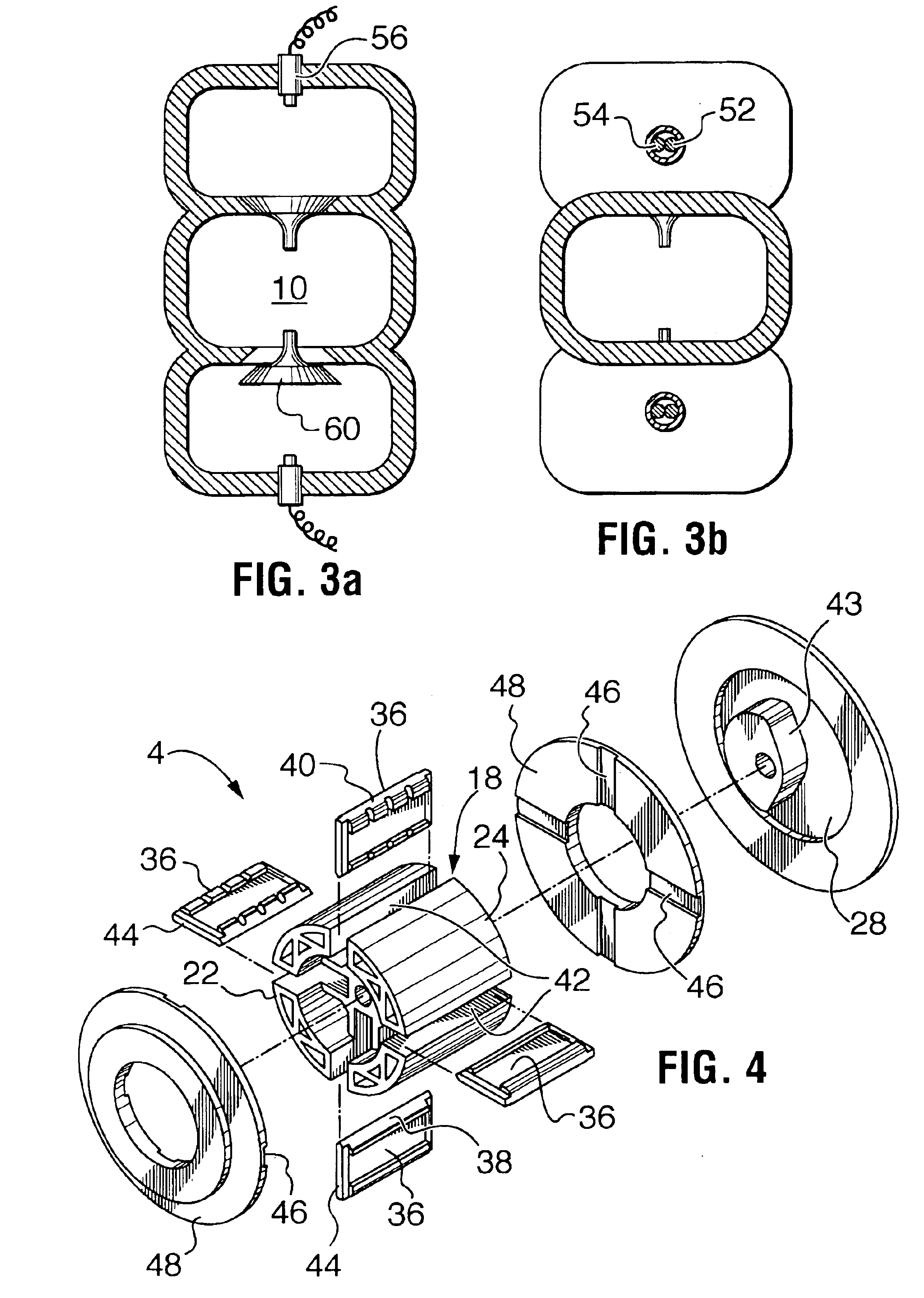
The fluid turbine 4 as can be seen in FIG. 2, operates in conjunction with a pair of chambers 6 and 8 and an exhaust chamber 10, which communicates with an exhaust pipe 12. Chambers 6 and 8 communicate with, respectively, ports 14 and 16 of fluid turbine 4. As will be described subsequently, chambers 6 and 8 and ports 14 and 16 can be arranged to have different functions, depending upon whether rotor 18 of fluid turbine 4 is driven to rotate in a clockwise or counter-clockwise direction.

As will be understood from a review of FIGS. 2 and 4, turbine 4 comprises rotor 18, which is secured to and drives a shaft 20. Rotor 18 has ends...


PUM


Abstract

An internal combustion rotary engine which includes a housing encased rotor having: cam actuated inwardly and outwardly extending vanes, a combustion chamber communicating with a fluid inlet port to the vanes within the housing, and an exhaust chamber communicating with the fluid outlet port from the vanes of the housing, air and fuel injectors associated with the combustion chamber for delivery of an air and fuel mixture to the combustion chamber, and igniter means associated with the combustion chamber for igniting air and fuel mixture within that chamber. Controls are provided to properly control the sequence of air and fuel injection, fuel ignition and exhaust valve opening and closing during operation of the engine to provide simpler and more economical rotary engine.

Description

FIELD OF THE INVENTIONThe present invention relates to an internal combustion rotary engine.BACKGROUND OF THE INVENTIONConventional internal combustion piston engines, used for powering motor vehicles and power generators and in numerous other applications have many shortcomings.To understand some of these shortcomings, one need only review the sequence of events in a single piston engine. Combustion of the air / fuel mixture in the cylinder head commences just before the piston reaches top dead center, to have good pressure applied when the connecting rod is at its most efficient position on the crankshaft (90.degree.). Therefore, depending upon flame front progression and the rpm of the engine, most of the high pressure occurs when the crankshaft lobe is still just off a vertical axis of the shaft center in the 10.degree. range. This results in much of the downward force from the piston being diverted from efficient rotary movement to the application of vertical pressure on the cran...

Claims


Application Information

Patent Timeline
Patent Type & Authority Patents(United States)
IPC IPC(8): F01C1/00F01C1/344F02P13/00F01C20/16F01C21/08F02B53/00F02B53/04
CPCF01C1/3441Y02T10/12F01C1/3442F02B53/06
Inventor PATTERSON, DAVID G.PATTERSON, ALBERT
Owner 1564330 ONTARIO
Why Eureka
Try Eureka