Slipring with a slide track formed as a closed circuit of electrically resistant material

a closed circuit, material technology, applied in the direction of rotary current collectors, inductances, selection arrangements, etc., can solve the problems of interference with the signal, inability to achieve reflection-free termination, increased production costs, etc., to improve signal transmission properties, reduce reflections, and improve the effect of signal transmission

Active Publication Date: 2009-06-16
SCHLEIFRING & APPBAU
View PDF18 Cites 3 Cited by
  • Summary
  • Abstract
  • Description
  • Claims
  • Application Information

AI Technical Summary

Benefits of technology

[0010]The invention is based on the object of improving sliprings or slide tracks in such manner that, in comparison with prior art, they exhibit improved signal transmission properties, in particular reduced reflections, and are simpler and more economical to manufacture.

Problems solved by technology

Particularly in the case of medium and high frequency signals, a problem with the arrangements is that of transmitting these signals along a slide track with as little interference as possible.
The disadvantage of this arrangement is that in fact no reflection-free termination can be achieved because of this so-called terminal resistor.
Reflections still occur at the position of the so-called terminal resistor and lead to interference with the signal.
This results in increased costs in production, and increased wear in the case of a sliding contact arrangement.
In fact, any advantage provided by the increased outlay is only very limited.
Multiple receptions of this kind can result in an impairment extending up to massive interference with the transmission.
However, slip rings which preferably have a brush running along a slide track cannot be manufactured economically to include a discontinuity Thus, for example, increased brush wear will occur at the site of the discontinuity.
In the case of high data rates of several 100 Mbit / s, this can lead to large losses of data.

Method used


Image

  • Slipring with a slide track formed as a closed circuit of electrically resistant material
  • Slipring with a slide track formed as a closed circuit of electrically resistant material
  • Slipring with a slide track formed as a closed circuit of electrically resistant material

Examples


Embodiment Construction

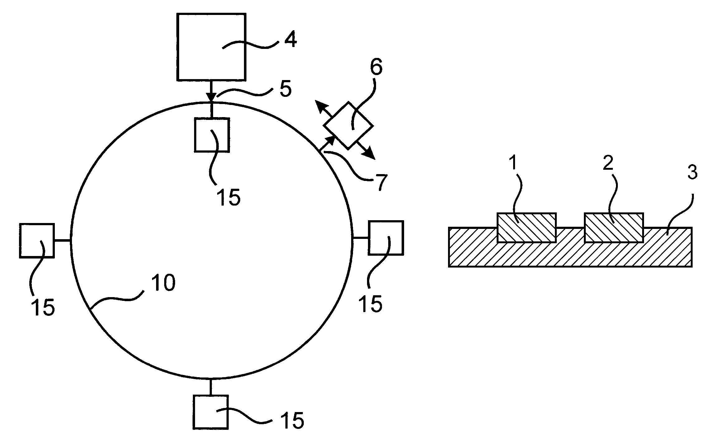
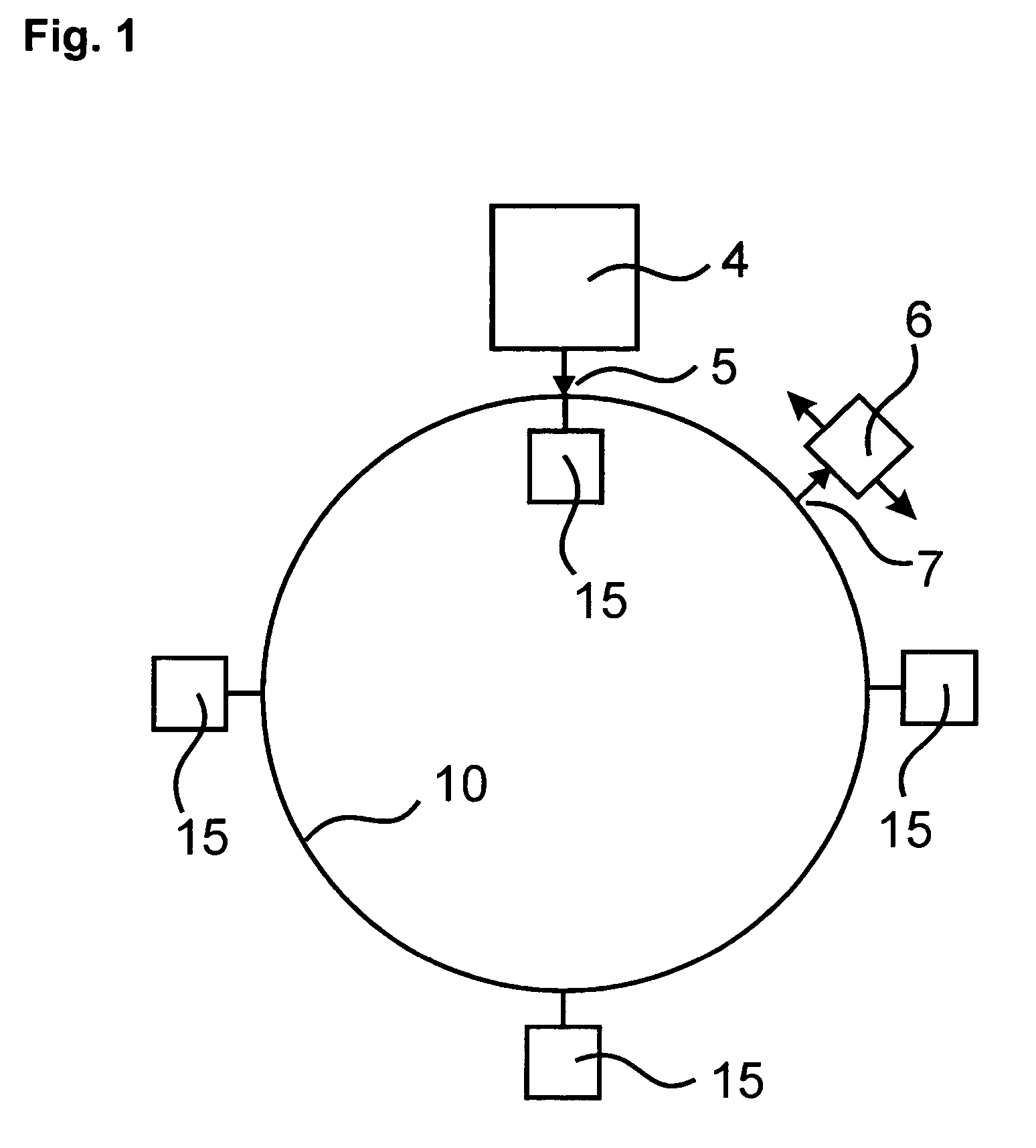
[0025]A device according to the invention for transmitting electrical signals or energy between at least two units that are moveable relative to each other comprises: at least one preferably circular and closed slide track of electrically conductive material disposed along a path of movement, and also at least one tap moveable along this slide track for coupling electrical signals in or out. Slide tracks in accordance with the invention cause an attenuation along their extent, which results in an attenuation of a signal transmitted via the slide track.

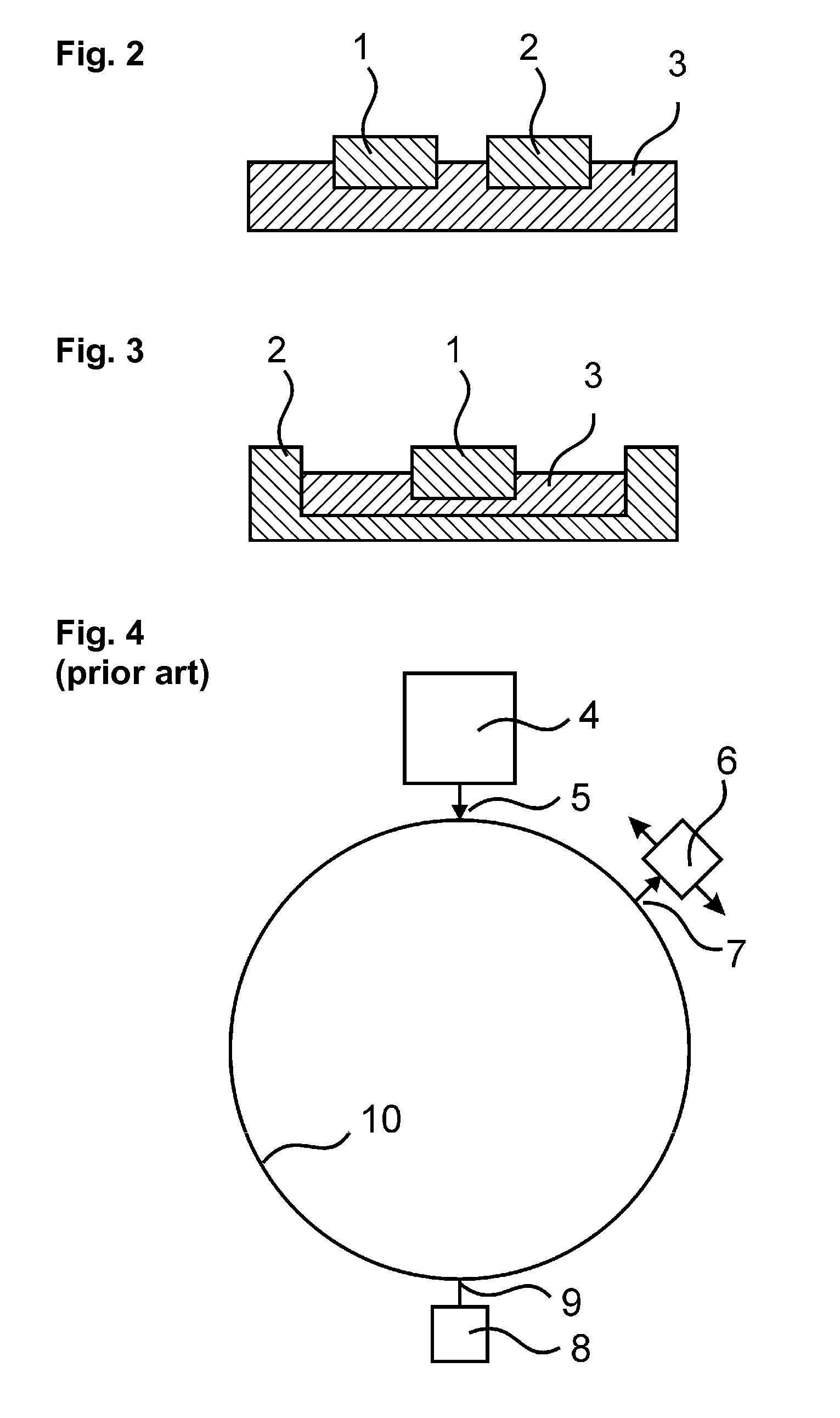
[0026]The prior art up to the present is based on a signal being transmitted via a slide track with as few losses as possible, and the slide track being terminated to be as free as possible from reflections at a discrete location. Investigations have shown that especially with closed slide tracks, a termination that is free from reflections cannot be achieved. However, closed slide tracks may be fabricated particularly economically, an...


PUM

PropertyMeasurementUnit
energyaaaaaaaaaa
electrically conductingaaaaaaaaaa
electricaaaaaaaaaa

Abstract

A device such as a slide track or a slipring for transmitting electrical energy or signals between at least two units that are rotatable relative to each other along a path of rotation comprises at least one slide track formed as a closed circuit of electrically conducting material disposed along the path of rotation, and at least one tap movable along the slide track for coupling electrical signals into the slide track from one of the units, or coupling electrical signals out of the slide track to one of the units. In order to reduce a superposition of signals that have traveled along different directions along the closed circuit, the at least one slide track is configured to have electric losses resulting in an amplitude of an electrical signal coupled into the slide track being reduced by at least 6 dB, preferably 10 dB, during a passage of the signal along one entire length of the slide track.

Description

CROSS REFERENCE TO RELATED APPLICATIONS[0001]This application is a continuation of pending International Application No. PCT / EP2004 / 004056 filed Apr. 16, 2004, which designates the United States and claims priority from pending German Application No. 103 19 248 filed on Apr. 28, 2003.BACKGROUND OF THE INVENTION[0002]1. Field of the Invention[0003]The invention relates to systems for electrical transmission between two units that are movable relative to each other. These are used, for example, in the form of linear slide tracks in linearly movable units such as crane systems, or as sliprings for rotating data transmission, for example in machine tools or computer tomographs.[0004]2. Description of the Related Art[0005]Both contacting and non-contacting transmission techniques are known for sliprings or slide tracks. Because sliprings for rotating data transmission, and linear or curved slide tracks operate on the same technical principle, no distinction will be made between them in t...

Claims


Application Information

Patent Timeline
Patent Type & Authority Patents(United States)
IPC IPC(8): H01R39/00H01F38/18H01R39/08
CPCH01F38/18H01R39/085
Inventor KRUMME, NILS
Owner SCHLEIFRING & APPBAU
Why Eureka
Try Eureka