Rotatable electrical coupling device

a coupling device and rotating technology, applied in the direction of electrically conductive connections, coupling device connections, rotary current collectors, etc., can solve the problems that the coupling design is not always suitable to meet the requirements, and achieve the effect of reducing contact area and minimising frictional interferen

Inactive Publication Date: 2015-01-06
ONDAL MEDICAL SYST
View PDF13 Cites 11 Cited by
  • Summary
  • Abstract
  • Description
  • Claims
  • Application Information

AI Technical Summary

Benefits of technology

[0012]By carefully selecting the geometry, material and dimensions of the conductors and the layer or mantle of dielectric material, the first and second coaxial connectors can be designed to have a specific characteristic impedance for high signal transmission performance with minimised reflection. For example, the characteristic impedance may be designed to be 30 Ohm, 50 Ohm or 75 Ohm, and is preferably designed to be within the range of 30 to 200 Ohm. Furthermore, by forming the first and second coaxial connectors fully shielded, little or no interference and little or no sensitivity to interference arises in transmission of the high-frequency and / or high-speed data signal via this coupling device.
[0016]In a preferred form of the invention, the coupling device includes at least one further (i.e. third) electrical contact member to provide an electrical connection between the first casing and the second casing. Thus, the third contact member operates to ensure that both of the first and second casings, which preferably serve as outer or shield conductors around inner or core conductors formed by the first and second electrical contact members respectively, remain grounded. In a highly preferred embodiment of the invention, the at least one biasing member is electrically conductive and thus forms the further (third) electrical contact member providing an electrical connection between the first casing and the second casing. Preferably, a plurality of biasing members (i.e. third contact members) is provided. Each biasing member (or third electrical contact member) may comprise, or be formed as, a spring element (e.g. a leaf-spring) and desirably presents a very small contact area for contacting the respective first or second casing. By providing a reduced contact area in this way, it is possible to minimise frictional interference during the relative rotation of the first and second connectors.
[0017]In a preferred form of the invention, the rotatable electrical coupling device further comprises a retaining member configured to secure or lock the second connector against removal from the coupled state with the first connector. For example, when the second connector is received within the first casing in the coupled state, the retaining member may be configured to secure or lock the second connector within the first casing. The retaining member is thus designed to prevent any inadvertent or unwanted removal of the second connector from the first connector, but without inhibiting the relative rotational movement of the first and second connectors. In this way, an inadvertent or unwanted disconnection of the coupling device can thus be avoided. The retaining member may, for example, be provided on, or as part of, the first casing to hold the second connector against removal from the first casing. In this regard, the retaining member may be formed as a cover or closure at an end of the first casing for substantially enclosing the second connector within the first casing. In an alternative embodiment, the first connector may be configured to be received by or within the second connector in the coupled state. As such, the retaining member may be configured to secure the first connector within the second casing, i.e. against inadvertent or unwanted removal of the first connector from the second connector. Thus, the retaining member is desirably configured to provide a releasable, axially capturing or secure attachment or coupling of the first and second connectors. In a highly preferred embodiment of the invention, the at least one biasing member is provided on the retaining member (e.g. inside a cover or closure at an end of the first casing) for contact or engagement with an outer surface of the second casing.
[0025]In a preferred form of the invention, at least one region of the second casing located adjacent the first casing in the coupled state is configured to reduce or minimise the frictional resistance during relative rotation of the second connector. The at least one region may, for example, comprise one or more abutting surface or journal surface for contact with the first casing. In this regard, each said abutting or journal surface preferably presents a small surface area, e.g. in the form of a narrow band or strip. Further, the at least one region of the second casing may be formed from or coated with a material having low friction properties. In an alternative embodiment, at least one region of the first casing located adjacent the second casing in the coupled state is configured to reduce or minimise frictional resistance during relative rotation of the second connector.
[0027]Thus, the invention provides an electrical coupling device specifically designed to provide for the transfer or transmission of high-frequency data signals and / or high-speed data signals, such as UHF, digital video, and digital HDTV signals, while still permitting rotation of the coupling through at least about 180°, preferably through at least about 360°, and more preferably with unlimited or full rotational flexibility permitting repeated rotation. Thus, the electrical coupling of the invention is able to provide for reliable transmission of high-frequency and / or high-speed data signals to and / or from one or more items of technical equipment mounted on an end of an articulated, rotatable support arm, with the coupling device and cables incorporated within the support arm.

Problems solved by technology

It has been found, however, that such coupling designs are not always suitable to meet the requirements demanded of equipment mounting systems in modern healthcare, commercial and industrial applications.
In particular, the technical equipment which is to be supported or suspended on such carrier arm systems often demand connection performance that is not provided by such prior art coupling arrangements.

Method used


Image

  • Rotatable electrical coupling device
  • Rotatable electrical coupling device
  • Rotatable electrical coupling device

Examples


Embodiment Construction

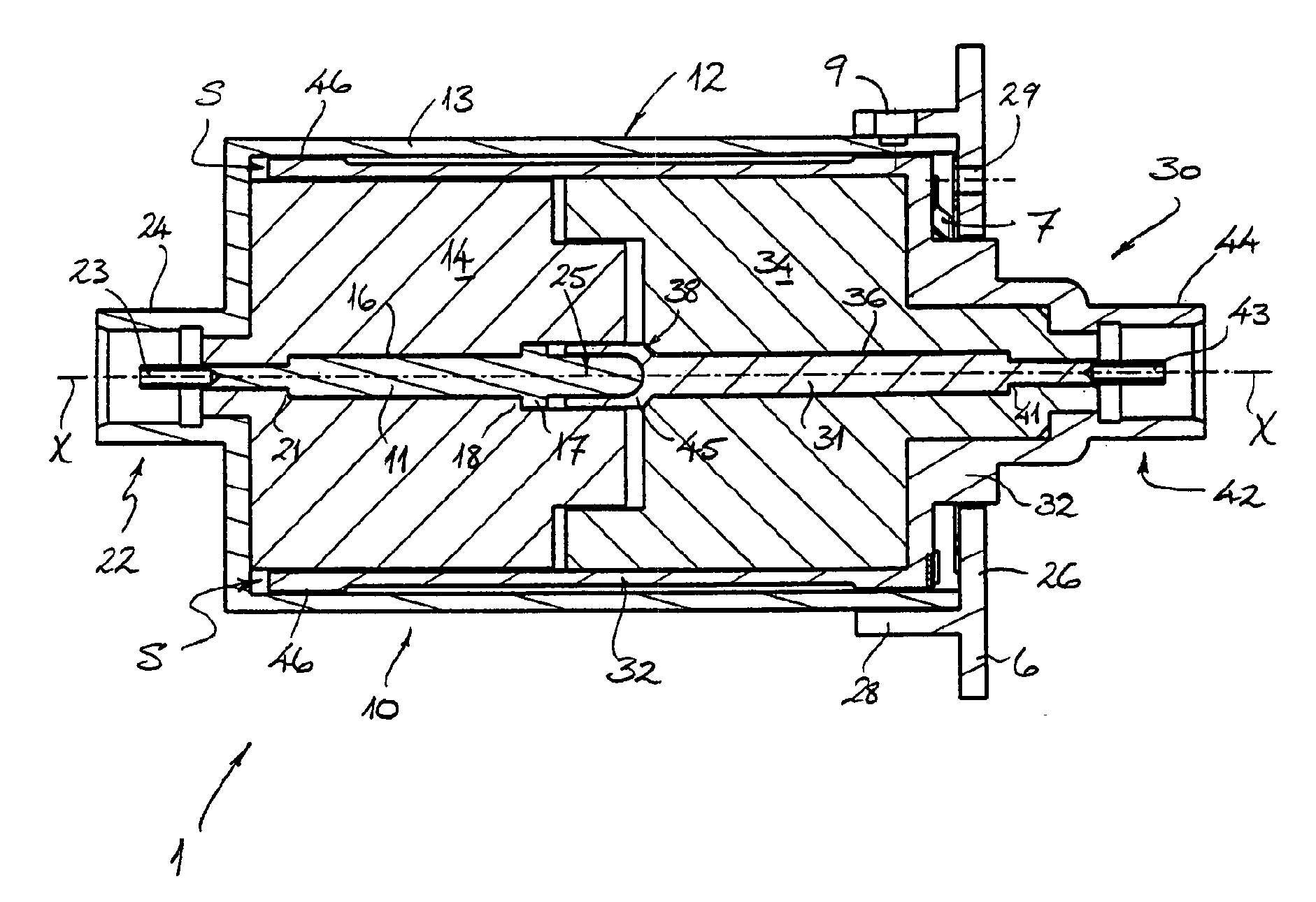
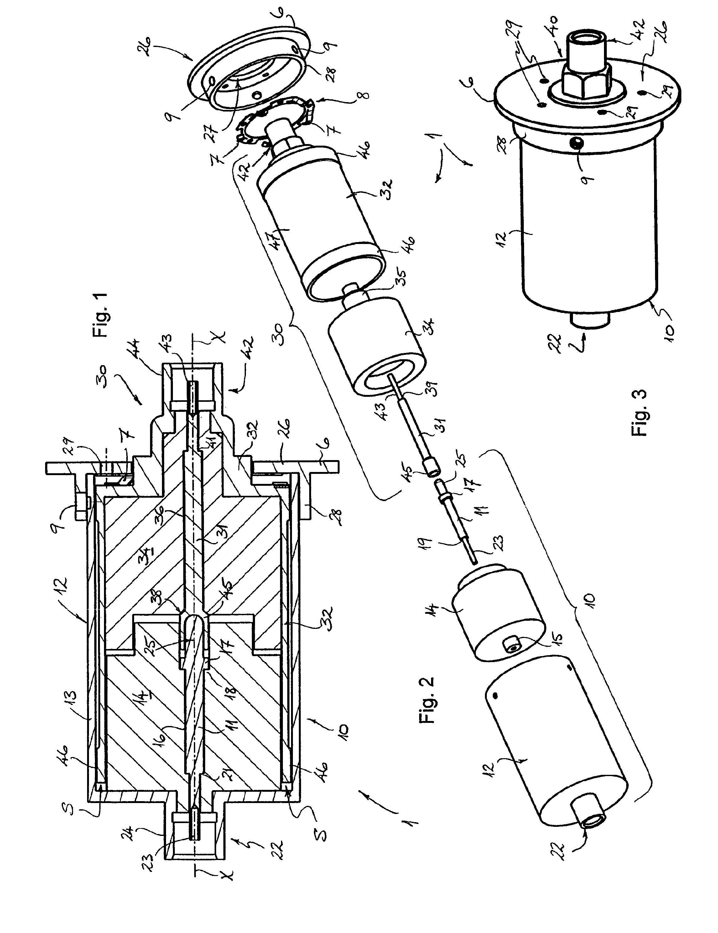
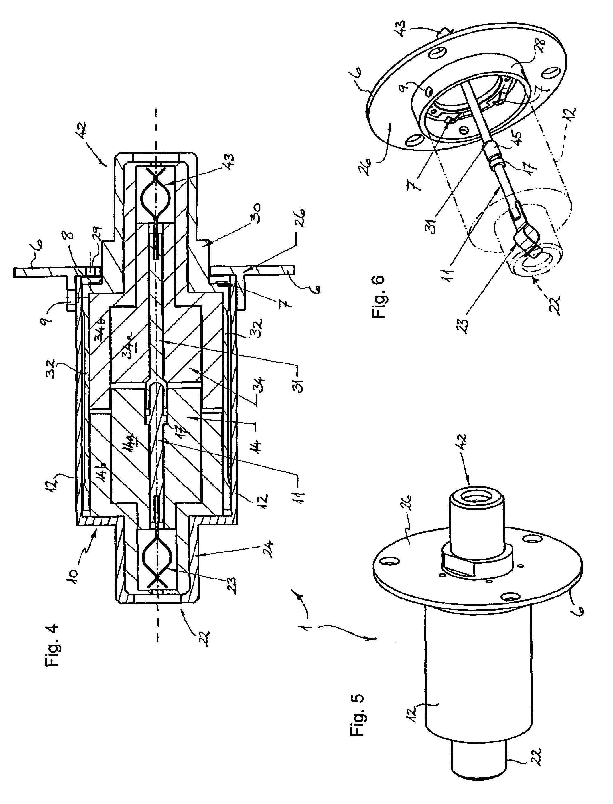
[0036]With reference firstly to FIGS. 1 to 3 of the drawings, a rotatable electrical coupling device 1 for a high-frequency and / or high-speed data transmission according to a preferred embodiment of the invention is illustrated. The electrical coupling device 1 has a first connector 10 and a second connector 30, which are shown in FIG. 1 and FIG. 3 of the drawings in a combined or coupled state in rotatable engagement with one another. The exploded view of the coupling device 1 in FIG. 2 more clearly illustrates the various components of each of the first and second connectors 10, 30.

[0037]With particular reference to FIGS. 1 and 2, therefore, the first connector 10 of the coupling device 1 can be seen to include a first electrical contact member 11 which is generally elongate and formed as a rod- or pin-like member. This rod- or pin-like first contact member 11 has a generally circular cross-section and extends centrally of the first connector 10. Furthermore, the first contact mem...


PUM


Abstract

A rotatable electrical coupling device incorporates a first connector having a first electrical contact member adapted to conduct or transmit a high-frequency and / or high-speed data signal, and a second connector having a second electrical contact member adapted to conduct or transmit a high-frequency and / or high-speed data signal. The second connector is configured to be coupled with the first connector for substantially free or unimpeded rotation about an axis (X) relative to the first connector, the first and second electrical contact members being configured to engage one another and to maintain uninterrupted electrical contact throughout a relative rotational movement between the first and second connectors in a coupled state.

Description

TECHNICAL FIELD[0001]The present invention relates to a rotatable electrical coupling device and, more particularly, to a coupling device configured to provide an uninterrupted electrical connection between coupled components throughout relative rotation thereof about a rotational axis of the device.[0002]The rotatable electrical coupling of the invention is desirably designed for use in a swivel or pivot joint of a mounting arm, such as the type of mounting arm used for supporting or suspending technical equipment, e.g. in medical or in commercial or industrial environments. In this way, the rotatable coupling of the invention is able to provide reliable electrical communication through the joint of the mounting arm to the technical equipment, regardless of rotary movement of that joint. As such, it will be convenient to hereinafter describe the invention in this particular context. It will be noted, however, that the rotatable electrical coupling device of the invention is not lim...

Claims


Application Information

Patent Timeline
Patent Type & Authority Patents(United States)
IPC IPC(8): H01R9/05H01R13/6471H01R13/6592H01R24/40H01R24/54H01R35/04H01R39/64H01R103/00
CPCH01R24/40H01R39/64H01R24/542H01R13/6471H01R2103/00H01R13/6592H01R35/04
Inventor GOBEL, ANDREASICKLER, FRITZ
Owner ONDAL MEDICAL SYST
Why Eureka
Try Eureka