Integral cooling system for rotary engine

a technology of integrated cooling system and rotary engine, which is applied in the direction of engine cooling apparatus, rotary piston engines, air transportation, etc., can solve the problem of little attention to providing a cooling system that is particularly adapted, and achieve the effect of compact and efficien

Active Publication Date: 2008-08-19
PRATT & WHITNEY CANADA CORP
View PDF35 Cites 36 Cited by
  • Summary
  • Abstract
  • Description
  • Claims
  • Application Information

AI Technical Summary

Benefits of technology

[0006]It is therefore an aim of the present invention to provide a compact and efficient cooling system for a rotary combustion engine.

Problems solved by technology

In such systems, however, little focus is given to providing a cooling system that is particularly adapted for integration in a compact package suitable for aircraft applications.

Method used


Image

  • Integral cooling system for rotary engine
  • Integral cooling system for rotary engine
  • Integral cooling system for rotary engine

Examples


Embodiment Construction

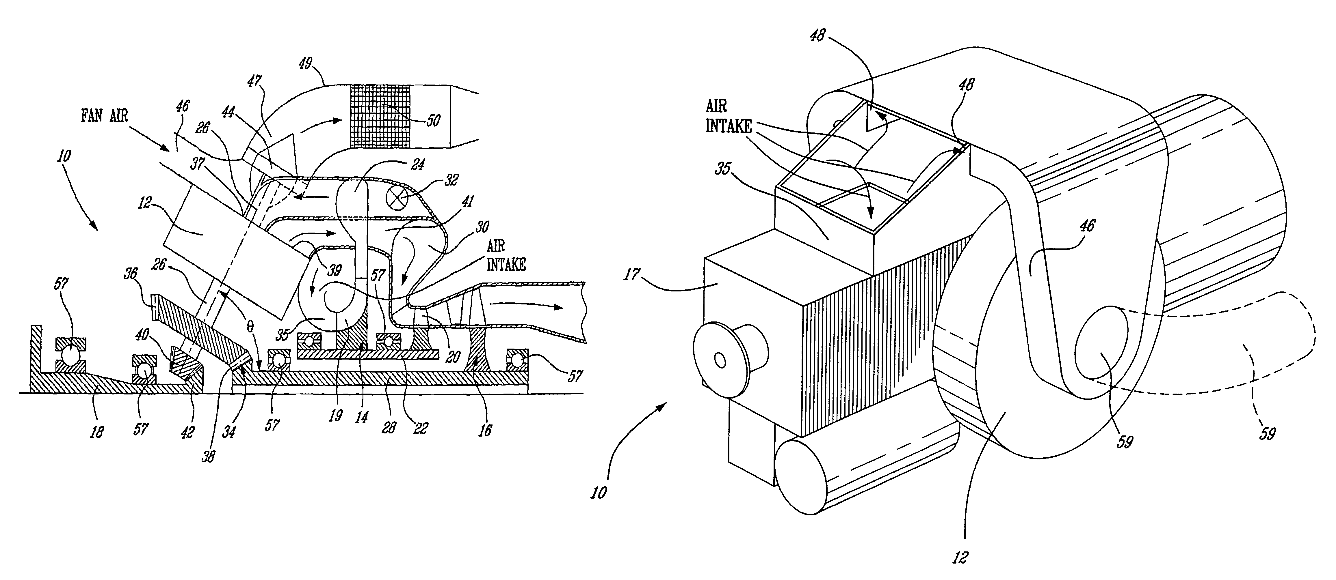
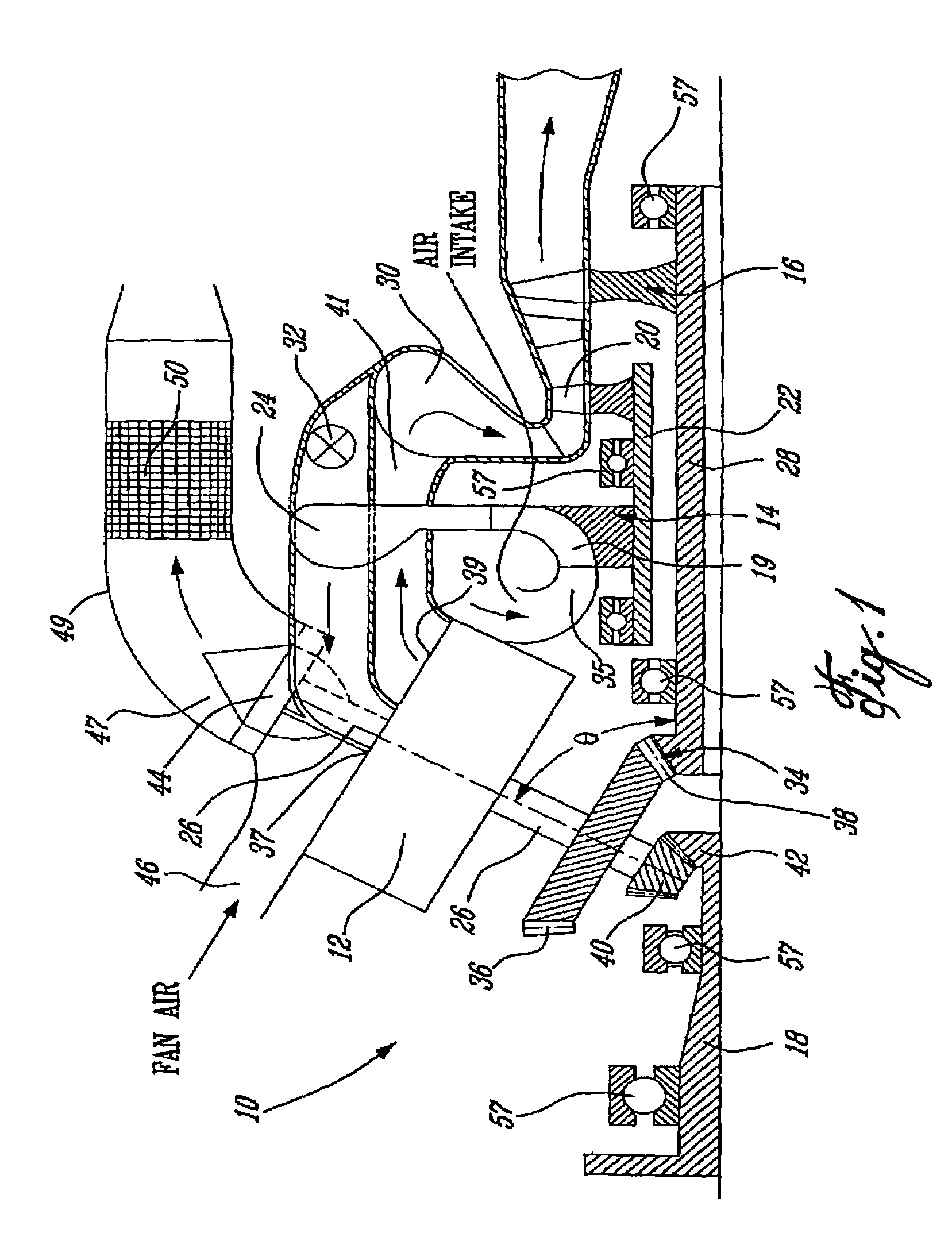
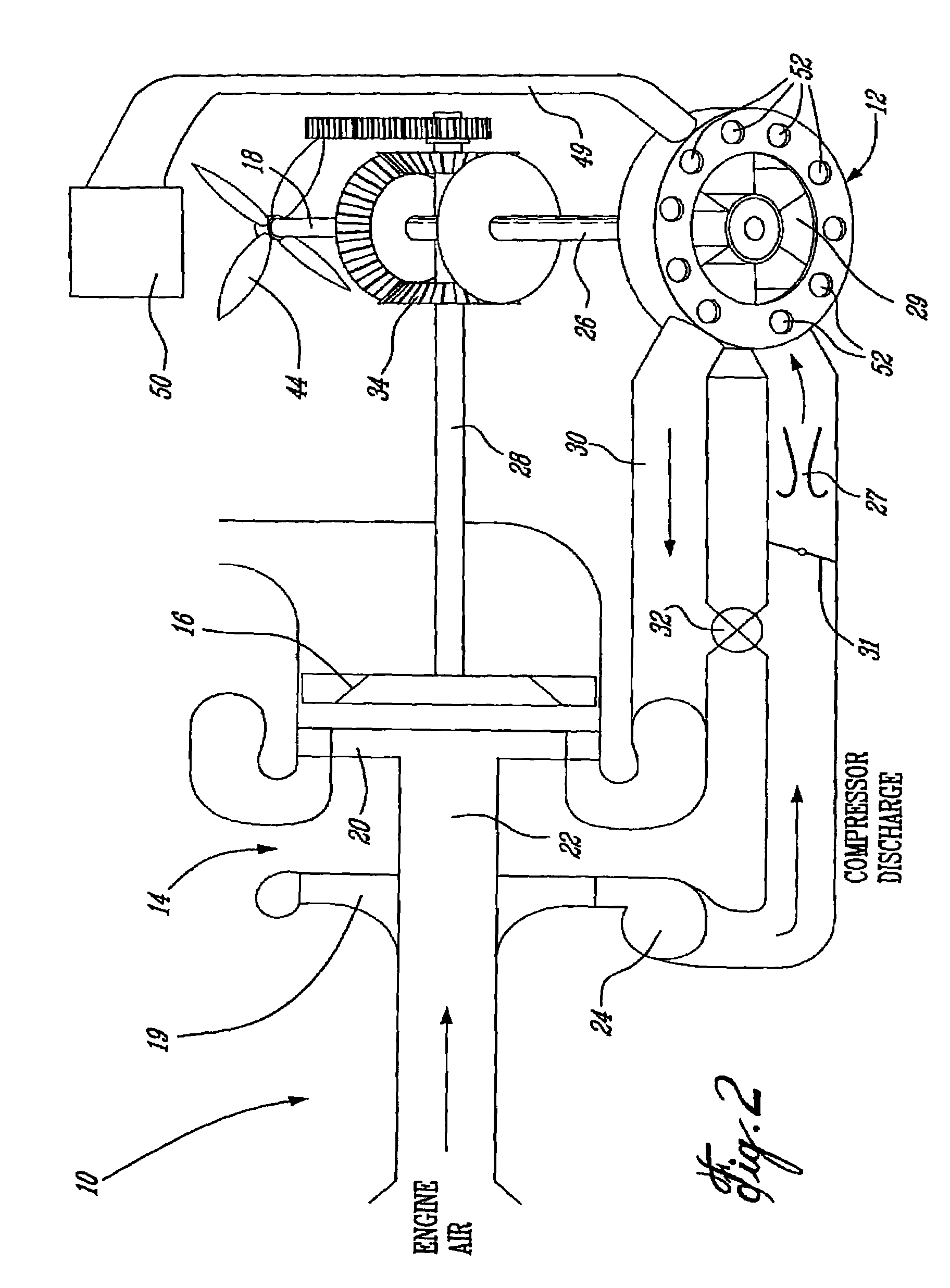
[0017]FIG. 1 is a schematic representation of a compound cycle engine 10 of a type preferably provided for use in a variety of aero applications, such as turboshaft, turboprop or APU (auxiliary power unit) applications. Referring to FIG. 1, it can be seen that the compound cycle engine 10 generally comprises at least one rotary cycle turbine topping device (TTD) 12 (preferably 1 or 2, as indicated in FIG. 1) and a gas turbine engine 14, which acts as a turbocharger. Turbocharger 14 comprises a compressor 19, a first stage turbine 20 and a second stage or power turbine 16. A hollow shaft 22 connects first stage turbine 20 to compressor 19. The power turbine 16 is preferably a free turbine and includes a power turbine shaft 28 concentrically disposed within the hollow shaft 22 for independent rotation with respect thereto. The shaft 28 connects power turbine 16 to rotary machine 12 via a bevel gearset 34. Preferably the bevel gear set 34 has a reduction gear ratio of 3:1. It is unders...


PUM


Abstract

A rotary combustion engine (12) with a self-cooling system comprises a heat exchanging interface for discharging excess heat from the rotary combustion engine (12), and a direct drive fan (44) integrated on the rotary engine output shaft (26) for providing a flow of forced air over the heat exchanging interface.

Description

RELATED APPLICATIONS(S)[0001]This application is a continuation of International Patent Application No. PCT / CA2004 / 000260 filed on Feb. 24, 2004, which claims benefit of Canadian Patent Application Nos. 2,419,691 and 2,419,692 filed on Feb. 24, 2003, all of which are herein incorporated by reference.BACKGROUND OF THE INVENTION[0002]1. Field of the Invention[0003]The present invention relates to cooling systems for rotary combustion engines and, more particularly, to an improved and compact cooling system suitable for integration with an aircraft compound cycle engine.[0004]2. Description of the Prior Art[0005]There have been attempts to develop compound cycle engines having internal combustion engines or other cycle-topping and turbine engines, coupled together to provide a common output. See, for example. U.S. Pat. No. 4,815,282. In such systems, however, little focus is given to providing a cooling system that is particularly adapted for integration in a compact package suitable f...

Claims


Application Information

Patent Timeline
Patent Type & Authority Patents(United States)
IPC IPC(8): F02G3/00F01C21/04F02K11/00F02K3/00F02K3/02F02K9/00F03C2/00F04C2/00F24B1/06F28F13/12F01D25/12F01D25/26F02C5/06F02C7/12F02C7/18F02K99/00
CPCF01D25/12F01D25/26F02C5/06F02C7/12F02C7/18Y10T74/1906Y02T50/671Y02T50/676F05D2260/20F05D2250/314Y02T10/12Y02T50/60
Inventor ULLYOTT, RICHARD
Owner PRATT & WHITNEY CANADA CORP
Why Eureka
Try Eureka