Swinging driver

A driving device, swinging technology, applied in the direction of rider driving, transportation and packaging, vehicle parts, etc., can solve the problems of high decomposition consumption, the driving position cannot move forward and backward at will, and tilt backwards, etc.

Inactive Publication Date: 2007-12-19
冉福生
View PDF0 Cites 2 Cited by
  • Summary
  • Abstract
  • Description
  • Claims
  • Application Information

AI Technical Summary

Problems solved by technology

[0002] The driving position of the existing rickshaw driving device cannot move forward and backward at will during driving. The obvious disadvantage of this structure is: when driving uphill or actively accelerating, the upper body can naturally tilt forward naturally, while the lower limbs cannot coordinate and balance at will when driving the vehicle. Move backwards; on the contrary, when driving downhill or actively slowing down, the upper body instinctively tilts backwards, and the lower limbs cannot move forward in coordination and balance at will while driving the vehicle
When it is necessary to adjust the acceleration of the movement, it is difficult for the cyclist to pedal in a straight line with the legs and the upper body, and the force used is consumed by the bending and decomposition of the body, which leads to easy fatigue of the legs and low operating efficiency of the driving vehicle

Method used


Image

  • Swinging driver
  • Swinging driver
  • Swinging driver

Examples


Embodiment 2

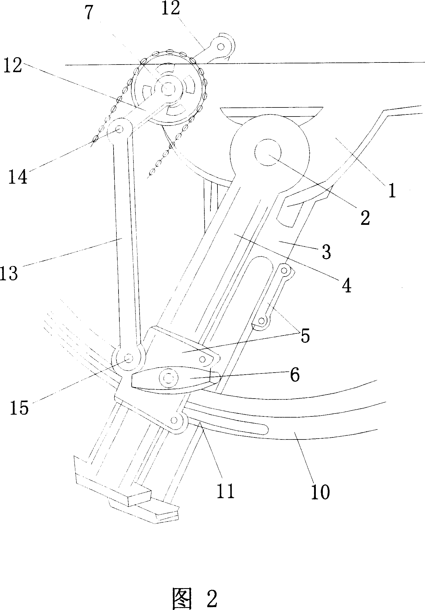
[0044] The main difference between embodiment 2 and embodiment 1 is that the transmission pair is different, and the transmission pair in embodiment 2 is a crank slider connecting rod transmission structure.

[0045] Figure 2 is a schematic diagram of the crank slider connecting rod transmission structure. As shown in Figure 2, the crank slider connecting rod transmission structure is: the transmission shaft 7 of the transmission mechanism, its left and right ends are respectively provided with a left and right crank 12 in a reverse straight line state, and the left and right slider structures 5 are respectively connected through the connecting rod. The rod 13 is hinged with the distal ends of the left and right cranks 12 on the same side, and the hinged structure is located at 14, 15, thus forming a transmission connection. Described left and right cranks 12 also can be the center of the transmission wheel on the power transmission shaft 7 and the connecting section close to ...


PUM


Abstract

The present invention discloses one kind of swinging driver, and aims at providing one kind of manpower driver with high balance of body during driving, capacity of raising running speed and power saving. The swinging driver consists of one manpower driving mechanism and one transmission mechanism. The transmission mechanism has one driving shaft fixed onto the frame, one driving and connecting structure to the wheels, and one swinging arm with upper end hinged to the swing shaft fixed on the frame and lower end capable of swinging around the swing shaft. The manpower driving mechanism on the swinging arm is connected to the transmission mechanism through the matching driving pair. The swinging driver may be applied in manpower cycle, especially manpower racing cycle, sports cycle, etc.

Description

1. Technical field [0001] The invention relates to a driving device, specifically a human driving device with a driving mechanism that can swing back and forth, which can be used in rickshaws or other vehicles that require human power. 2. Technical Background [0002] The driving position of the existing rickshaw driving device cannot move forward and backward at will during driving. The obvious disadvantage of this structure is: when driving uphill or actively accelerating, the upper body can naturally tilt forward naturally, while the lower limbs cannot coordinate and balance at will when driving the vehicle. On the contrary, when driving downhill or actively slowing down, the upper body will naturally tilt backwards, and the lower limbs cannot move forward in coordination and balance at will while driving the vehicle. When it is necessary to adjust the acceleration of the movement, it is difficult for the cyclist to pedal in a straight line with the legs and the upper bod...

Claims


Application Information

Patent Timeline
IPC IPC(8): B62M1/04B62M1/24
Inventor 冉福生
Owner 冉福生
Why Eureka
Try Eureka