Section speed reducing magnetic control system for sports appliance
A sports equipment and segmented technology, which is applied in the field of magnetic control systems, can solve the problems of insufficient refinement of the control range, difficult control, and small adjustment of the number of speed segments. The effect of reuse
- Summary
- Abstract
- Description
- Claims
- Application Information
AI Technical Summary
Problems solved by technology
Method used
Image
Examples
Embodiment 1
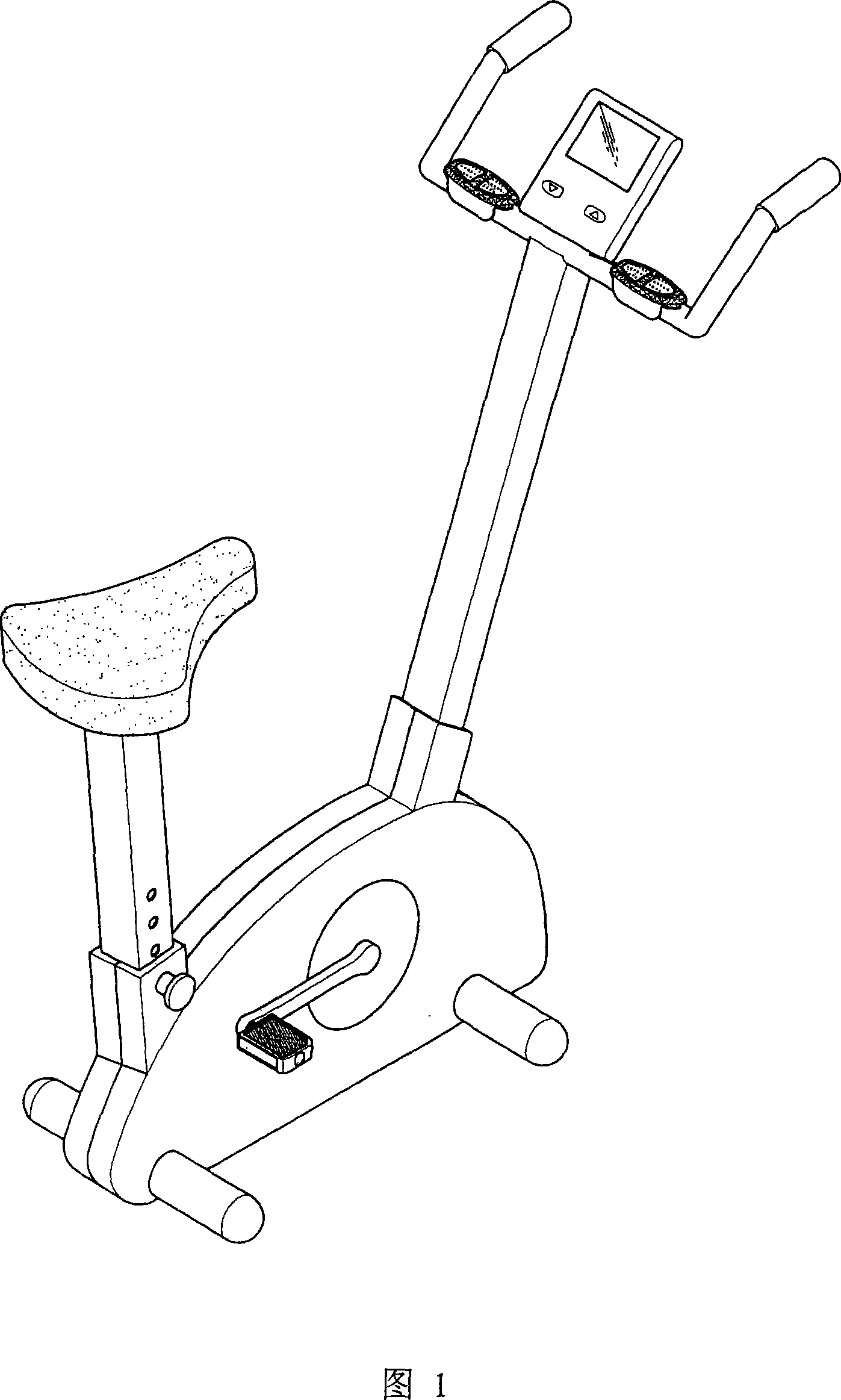
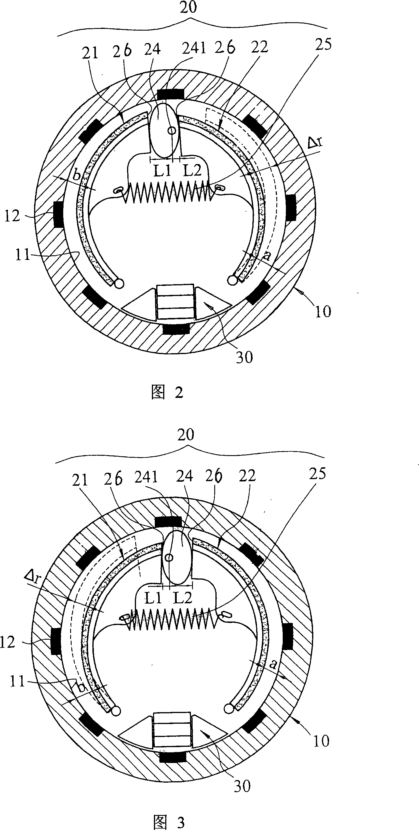
[0055]Please refer to Fig. 1~Fig. 3 at first, a kind of sports equipment segmental deceleration magnetic control system provided by the present invention mainly includes: a flywheel body 10, a magnetic control group 20 located in the flywheel body, and a Genset 30.
[0056] The flywheel body 10 is made of aluminum alloy, and it is concavely provided with a chamber 11, which is in the shape of a circular groove, and the inner edge wall of the chamber 11 is equidistantly provided with eight magnetic conductors 12 with magnetic conduction effect. , which can be a magnet. The magnetic conductor 12 is embedded in the inner wall of the container, and its magnetically conductive surface is exposed at the inner edge of the container.
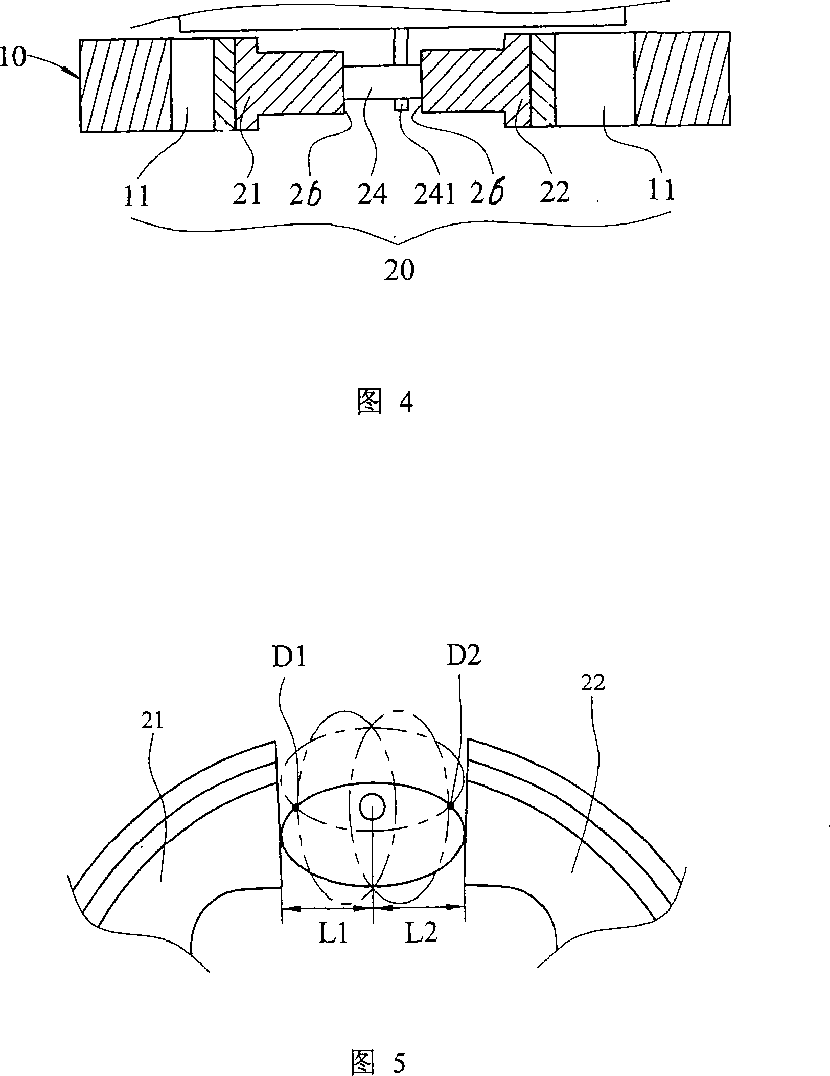
[0057] The magnetic control group 20 is located in the chamber 11, and has two magnetic control units 21, 22, which are arranged oppositely, and can be rotated and deflected respectively, and can be formed with each of the above-mentioned magnetizers 1...
Embodiment 2
[0067] Figure 6 shows Embodiment 2 of the present invention, which differs from Embodiment 1 in that the setting of the magnetron group 20 is offset from the center of the circular groove-shaped chamber 11; and the abutting member 24 is a cam with an irregular profile. The pivot point 241 is arranged at the eccentric position of the cam. The cam can rotate around the pivot point 241; 21, 22 are respectively separated from each magnetizer 12 by different gaps.
Embodiment 3
[0069] Figure 7 shows Embodiment 3 of the present invention. In this embodiment, the magnetron group 20 has an abutting surface 26, which provides a position for abutting against the abutting member 24, and the abutting surface is a predetermined irregular contour. , the curvature of the profile surface changes; the abutment member 24 is elliptical as shown in the figure, and its pivot point 241 is located outside the major axis and the minor axis, so its effective adjustment stroke is the distance of the entire ellipse perimeter length, with Gain the effect of adjusting the number of speed segments of the effective stroke; with the help of the curvature change of the abutting surface 26 and the driving of the abutting member 24, the magnetic controls 21 and 22 can be effectively deflected respectively and have different distances from the magnetic conductor 12 adjustments for changes.
PUM
 Abstract
Description
Claims
Application Information
 - R&D
- Intellectual Property
- Life Sciences
- Materials
- Tech Scout
- Unparalleled Data Quality
- Higher Quality Content
- 60% Fewer Hallucinations
Browse by: Latest US Patents, China's latest patents, Technical Efficacy Thesaurus, Application Domain, Technology Topic, Popular Technical Reports.
© 2025 PatSnap. All rights reserved.Legal|Privacy policy|Modern Slavery Act Transparency Statement|Sitemap|About US| Contact US: help@patsnap.com


