Magnetron

A magnetron and tube shaft technology, applied in the field of magnetron, can solve the problems of increasing the working space, cost increase, and unavoidable cost increase, etc., and achieve the effect of miniaturization and improvement of oscillation output efficiency

Active Publication Date: 2007-12-26
TOSHIBA HOKUTO ELECTRONICS CORP
View PDF1 Cites 7 Cited by
  • Summary
  • Abstract
  • Description
  • Claims
  • Application Information

AI Technical Summary

Problems solved by technology

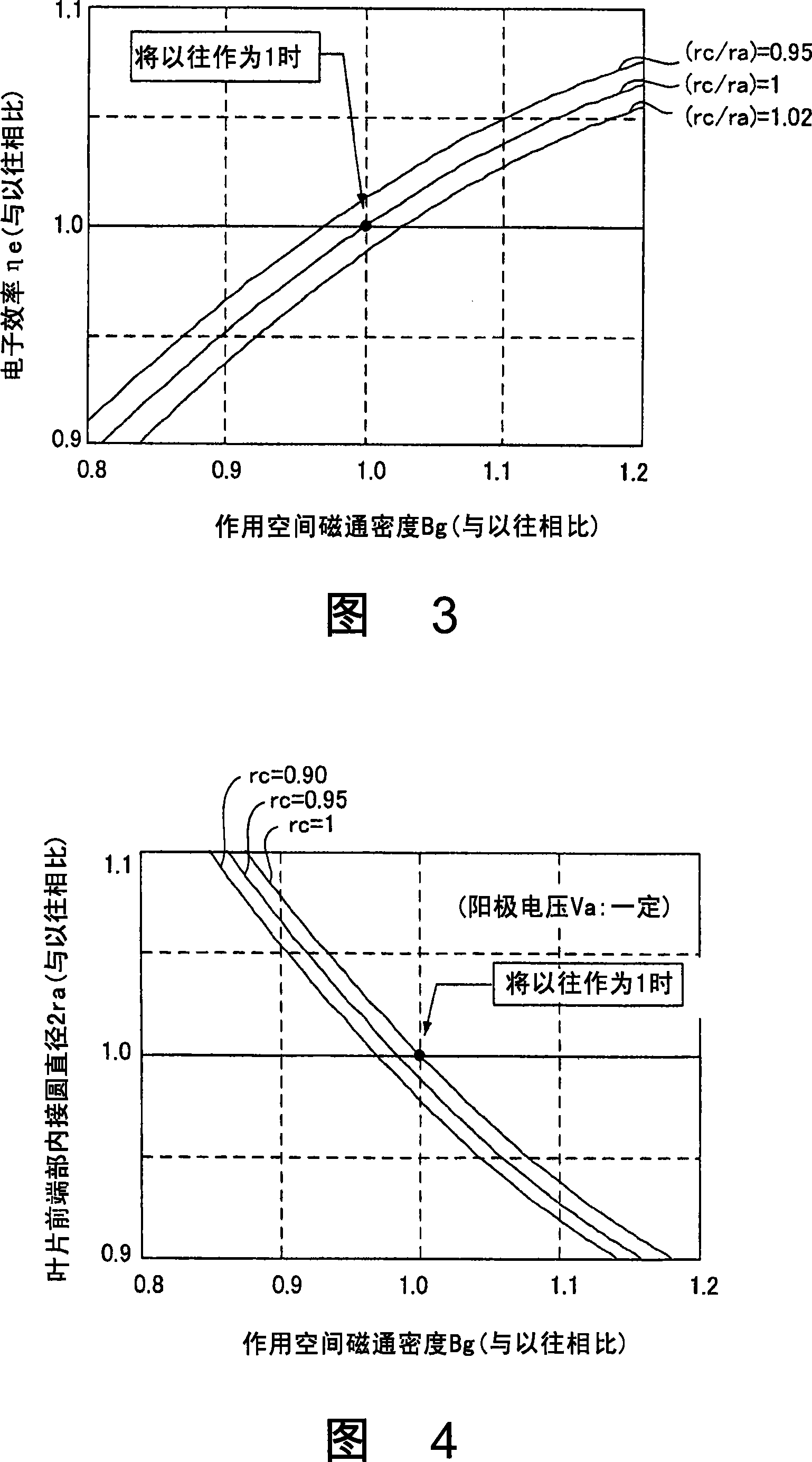
However, in conventional magnetrons, although the anode voltage can be further increased to increase the oscillation output efficiency by 1 to 2%, since it is necessary to further increase the magnetic flux density Bg in the action space, there is a problem that Permanent magnets will increase in size or performance, and the insulation and withstand voltage of the drive power supply will be required due to the increase in voltage, which will lead to an increase in cost
[0009] In addition, when developing a new type of magnetron, in order not to increase the anode voltage Va, the design method adopted is to reduce the diameter 2ra of the inscribed circle at the front end of the vane, but in order to improve the oscillation output efficiency, it is necessary to increase the magnetic field in the action space. The flux density Bg cannot avoid the cost increase due to the increase in size

Method used


Image

  • Magnetron
  • Magnetron
  • Magnetron

Examples


Embodiment Construction

[0045] Hereinafter, embodiments of the present invention will be described with reference to the drawings.

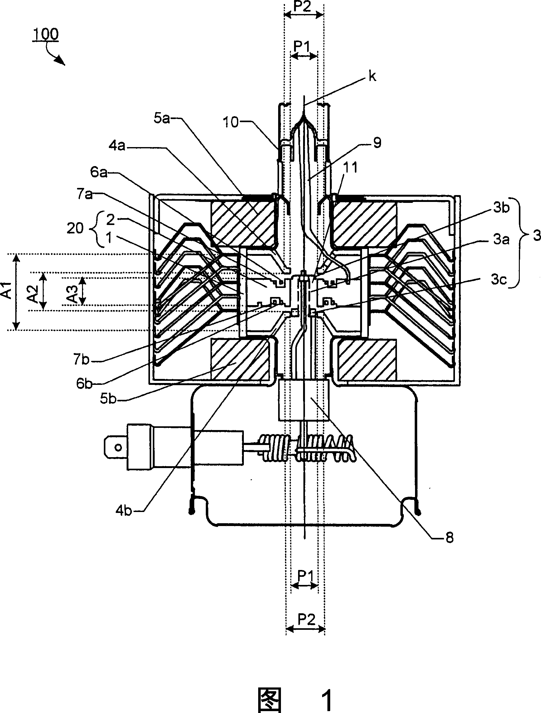
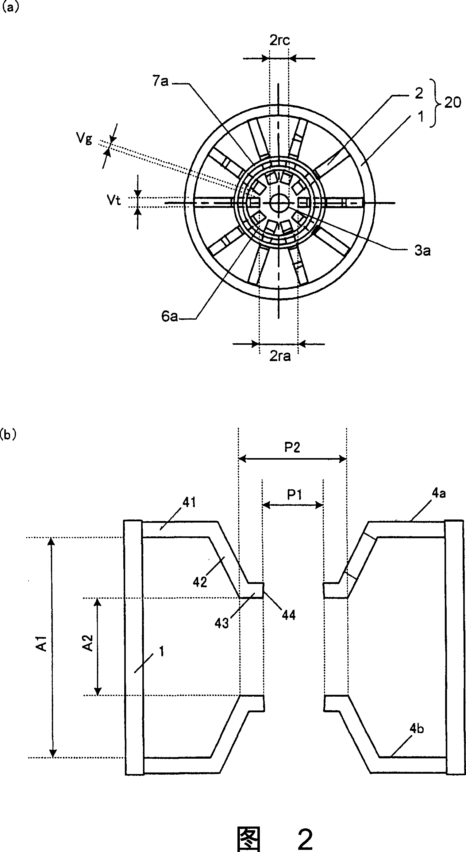
[0046] FIG. 1 is a sectional view of main parts of a main body of a magnetron 100 according to this embodiment. In addition, FIG. 2( a ) is a schematic top view showing main parts of the anode portion 20 and cathode portion 3 of the extracted magnetron 100 , and FIG. 2( b ) is an enlarged view of the pole pieces 4 a and 4 b.

[0047] As shown in Figure 1 and Figure 2 (a), the oscillating body part of the magnetron 100 has: an anode cylinder 1 and a plurality of blades 2 arranged radially from the inner wall of the anode cylinder 1 to the tube axis k at equal intervals An anode part 20 constituted; and a cathode part 3 having a helical filament 3a disposed inside the anode cylinder 1 along the tube axis k. A pair of end caps 3b, 3c are provided at both ends of the filament 3a.

[0048] The outer end of the blade 2 is fixed on the inner wall of the anode cylinder 1, and...


PUM


Abstract

At an oscillation frequency of 2450 MHz band, number of the vanes constituting the anode part of the magnetron being, the diameter 2 ra of the circle inscribing tip portions of the vanes on the cathode side being 8.0 to 8.8 mm, the diameter 2 rc of the outer periphery of the filament constituting the cathode part being 3.5 to 3.9 mm, the height A 3 of the vane in the direction of the tube axis is 7.0 to 8.0 mm, the mutual distance A 1 between the bases of the pair of funnel-shaped pole pieces fixed to both sides of the anode part being 21.5 to 23.5 mm, the mutual distance A 2 between the bottom portions of the pair of pole pieces being 10.2 to 11.2 mm, the inner diameter P 1 of the through-hole of the pole piece being 8.3 to 8.5 mm, and the outer diameter P 2 of the bottom portion being 11.0 to 16.0 mm are set up.

Description

technical field [0001] This invention relates to magnetrons used in microwave heating equipment. Background technique [0002] A magnetron is an electron tube that generates microwaves and is used in microwave heating equipment such as microwave ovens. The oscillating body portion of the magnetron has: an anode portion formed by an anode cylinder and a plurality of vanes arranged radially from the inner wall of the anode cylinder to the tube axis; and a helical blade arranged along the tube axis of the anode cylinder The cathode portion of the filament. At both ends of the anode cylinder, that is, the output part side and the input part side, a pair of funnel-shaped magnetic pole pieces having a root connected to the anode cylinder and a planar bottom forming a through hole in the center are provided facing each other. Ring-shaped permanent magnets are respectively provided on a pair of pole pieces (for example, refer to Patent Document 1). [0003] In such a configuratio...

Claims


Application Information

Patent Timeline
Patent Type & Authority Applications(China)
IPC IPC(8): H01J25/587H01J23/20
CPCH01J25/587H01J23/20H01J23/10H01J23/12
Inventor 加藤直也东正寿川口敏夫林伸司
Owner TOSHIBA HOKUTO ELECTRONICS CORP
Why Eureka
Try Eureka