Compact type lamp

A compact, lamp technology, applied in lighting devices, fixed lighting devices, electric light sources, etc., can solve the problems of volume limitation and the lamp is not compact enough, and achieve the effect of reducing the volume

Inactive Publication Date: 2008-01-02
KONINKLIJKE PHILIPS ELECTRONICS NV
View PDF0 Cites 0 Cited by
  • Summary
  • Abstract
  • Description
  • Claims
  • Application Information

AI Technical Summary

Problems solved by technology

However, in a lamp having a lamp housing-mounting plate structure as shown in FIG. Means that the volume of the lamp is limited by the space of the bulb and the space of the lamp housing
Thus, such lamps are still not compact enough

Method used


Image

  • Compact type lamp
  • Compact type lamp

Examples


Embodiment Construction

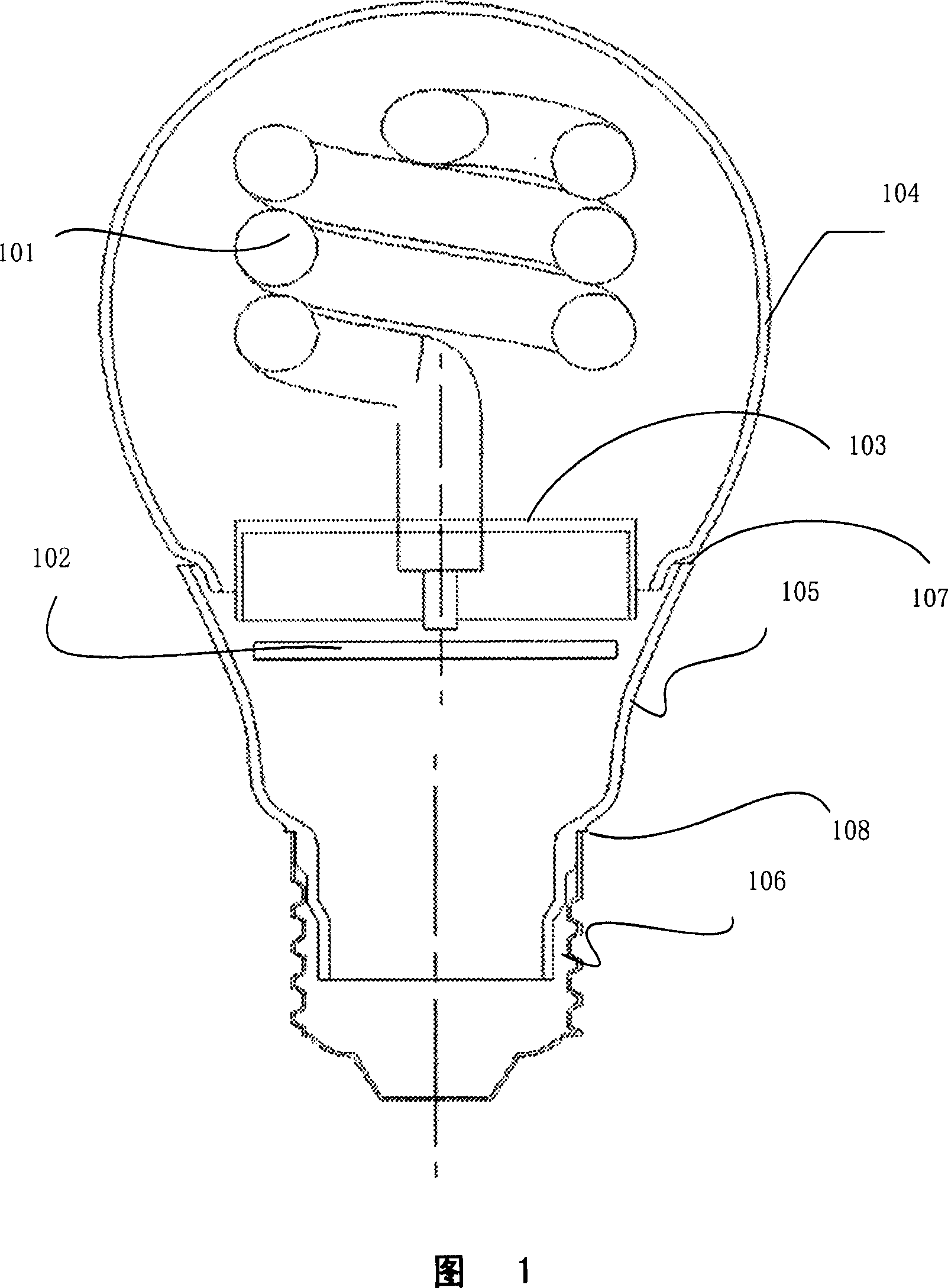
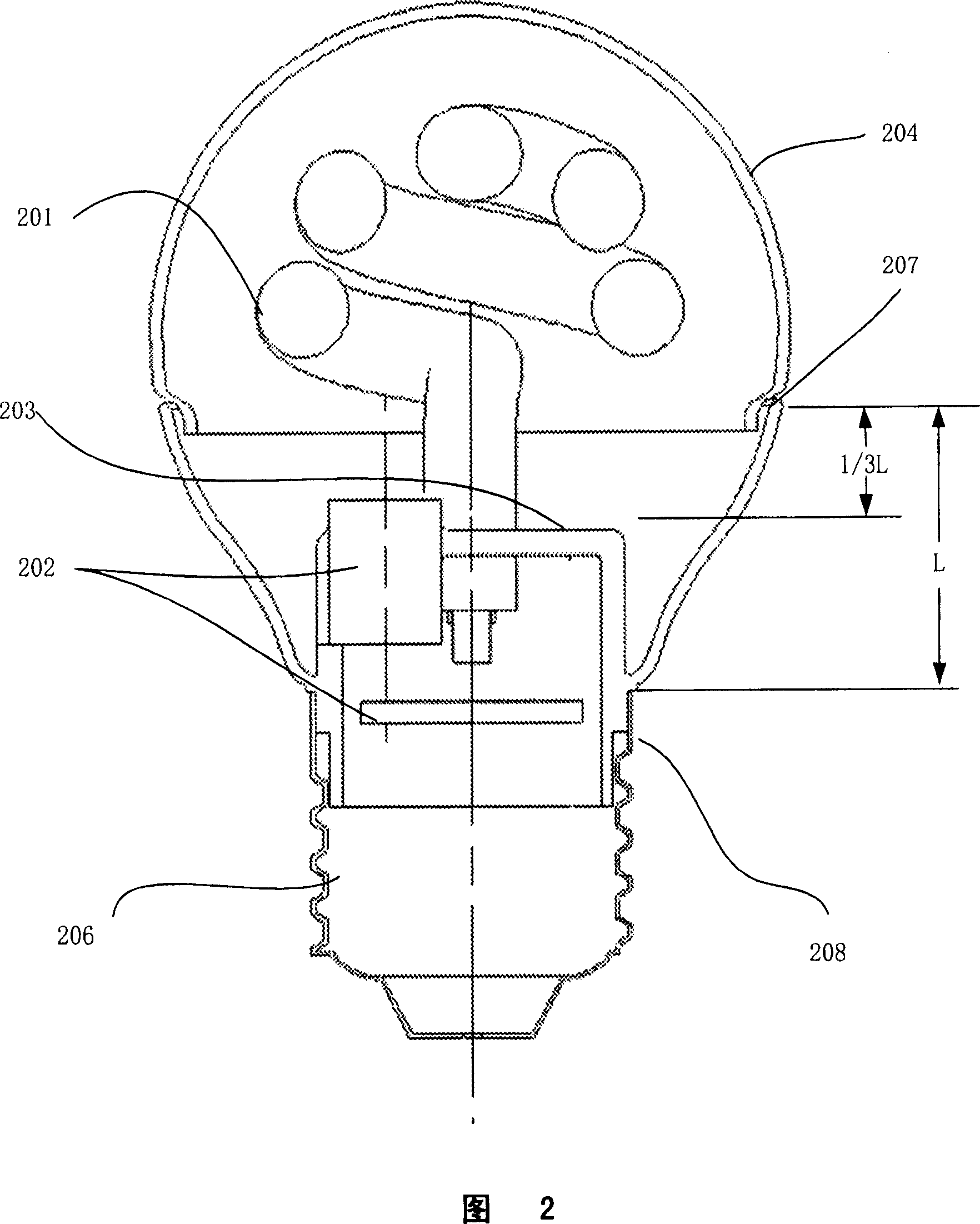
[0013] Fig. 2 schematically depicts a compact fluorescent lamp according to the present invention. The lamp comprises: a lamp tube 201; a circuit device 202 electrically connected to the lamp tube 201 for driving the lamp tube 201; a mounting plate 203 for installing the lamp tube 201 and the circuit device 202; a bulb 204, used to accommodate the lamp tube 201; a lamp housing 205, connected to the bulb 204, used to accommodate the mounting plate 203 and the circuit device 202; and a lamp holder 206, connected to the lamp housing 205 and electrically connected to the circuit device 202 for connecting to a power supply. The lamp housing 205 is connected with the bulb 204 at the bulb edge 207 of the lamp housing, and connected with the lamp base 206 at the lamp base edge 208 of the bulb. The lamp is characterized in that part of said circuit arrangement 202 is located in the space between the mounting plate 203 and the bulb 204 .

[0014] The luminous efficiency of fluorescent...


PUM


Abstract

The invention discloses a compacted lamp, which is characterized by the following: comprising a lamp tube, a circuit device, a assembled plate, a bulb and a lamp body; connecting the lamp tube with the circuit device; driving the lamp tube; assembling the lamp tube and the circuit device with the assembled plate; containing the lamp tube with the bulb; connecting the lamp body to the bulb; containing the assembled plate and the circuit device with the lamp body; arranging part of circuit device between the assembled plate and the bulb. This invention can get a more compact lamp than now lamp.

Description

technical field [0001] The present invention relates to a compact lamp, for example, a compact fluorescent lamp; the present invention also relates to the application of the lamp in the lighting field. Background technique [0002] Today the application of compact lamps has become a real need. For example, compact fluorescent lamps have replaced traditional straight fluorescent lamps in many occasions because compact fluorescent lamps are more compact. [0003] Figure 1 schematically depicts a known compact fluorescent lamp. The lamp comprises: a lamp tube 101; a circuit device 102 electrically connected to the lamp tube 101 for driving the lamp tube 101; a mounting plate 103 for installing the lamp tube 101 and the circuit device 102; a light bulb 104, used to accommodate the lamp tube 101; a lamp housing 105, connected to the bulb 104, used to accommodate the mounting plate 103 and the circuit device 102; a lamp cap 106, connected to the lamp housing 105, and It is elec...

Claims


Application Information

Patent Timeline
IPC IPC(8): F21S8/00F21V23/00
Inventor 彭鲲段晓青
Owner KONINKLIJKE PHILIPS ELECTRONICS NV
Why Eureka
Try Eureka