Light sensing display apparatus and display panel thereof

A technology for display panels and display devices, applied in directions such as static indicators

Inactive Publication Date: 2008-01-02
WINTEK CORP
View PDF3 Cites 10 Cited by
  • Summary
  • Abstract
  • Description
  • Claims
  • Application Information

AI Technical Summary

Problems solved by technology

It can avoid the aesthetic problems caused by too large opening area and improve the photosensitive angle more comprehensively, which can effectively improve the photosensitive efficiency

Method used


Image

  • Light sensing display apparatus and display panel thereof
  • Light sensing display apparatus and display panel thereof
  • Light sensing display apparatus and display panel thereof

Examples


Embodiment Construction

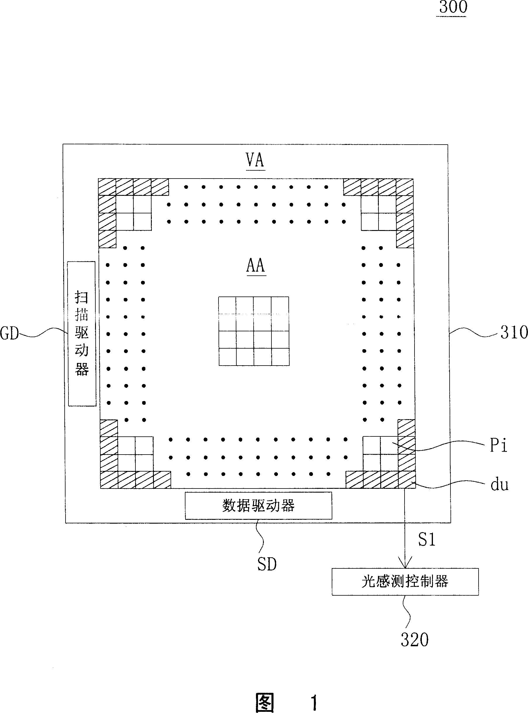
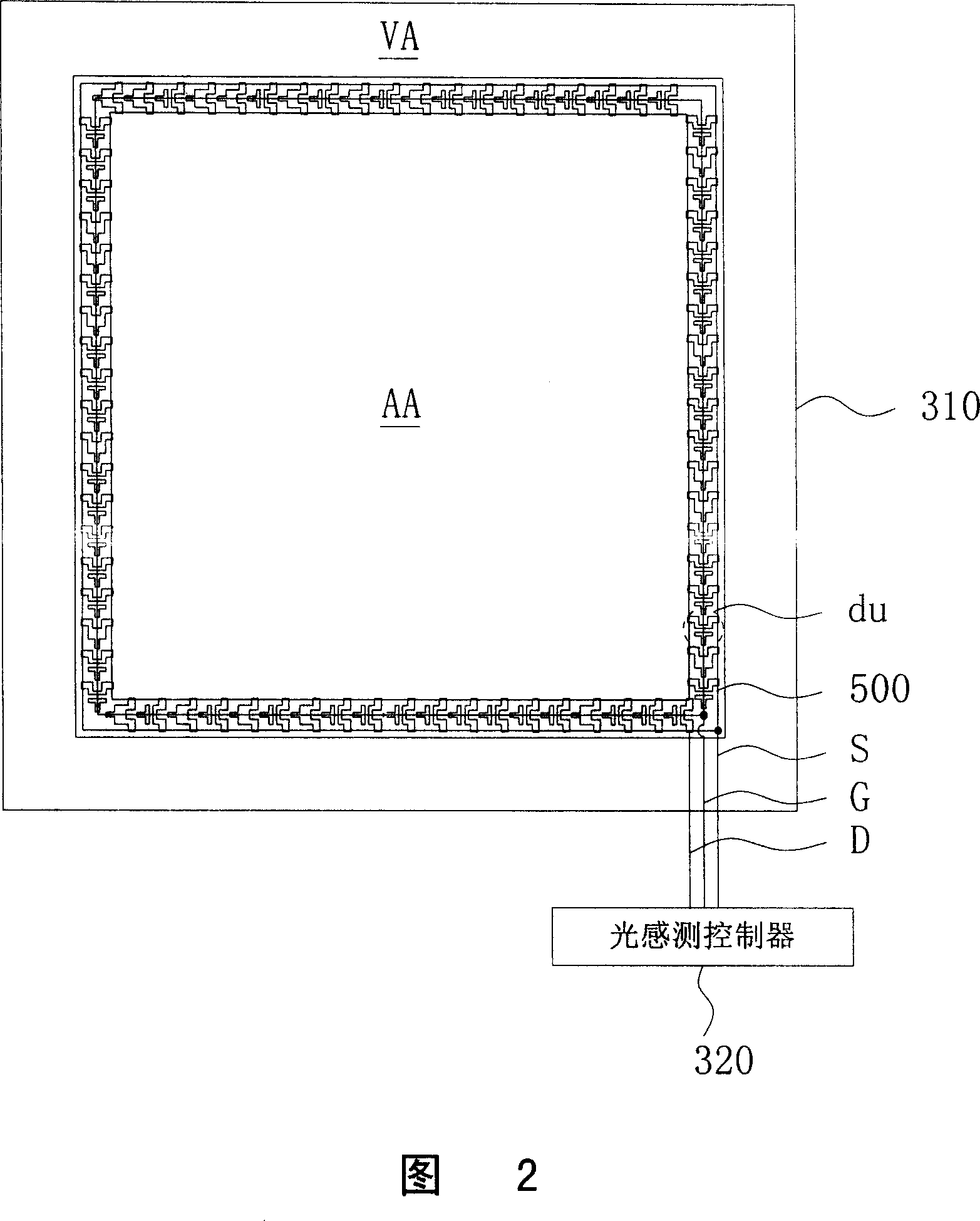
[0015] Please refer to FIGS. 1 and 2 at the same time. FIG. 1 is a schematic diagram of a photo-sensing display device according to a preferred embodiment of the present invention, and FIG. 2 is a schematic diagram of the connection of virtual sub-pixels in the display panel of FIG. 1 . As shown in FIGS. 1 and 2 , the light-sensing display device 300 includes a display panel 310 and a light-sensing controller 320 . The display panel 310 includes a display area AA, a non-display area VA, a plurality of sub-pixels pi and at least one dummy sub-pixel (dummy sub-pixel) du, for example, a plurality of dummy sub-pixels du. The non-display area VA is arranged around the display area AA. The sub-pixels pi are disposed in the display area AA for displaying images. Each dummy sub-pixel du has a photo-sensing component for sensing the intensity of light and outputting a photo-sensing signal S1. A data driver SD and a scan driver GD are disposed on the non-display area VA to control the...


PUM


Abstract

A kind of optical sensing device includes a display panel and a optical sensing controller. The display panel includes a display area, a non-display area, and several sub-pixels and at least one void sub-pixel. The non-display area circles the display area. The sub-pixels are set in the display area to display the image. Besides, the void sub-pixel is also set in the display area and possesses an optical sensing subassembly. The optical sensing controller and optical subassembly are coupled.

Description

(1) Technical field [0001] The present invention relates to a display device and a display panel thereof, and in particular to a light-sensing display device and a display panel thereof, which use virtual sub-pixels to sense ambient brightness. (2) Background technology [0002] The external environment has considerable influence on the display effect of the display device. For example, under a bright external light source, the picture is brighter. But in a darker environment, there will be moire phenomenon, and the picture is too bright to cause eye fatigue. The black floating phenomenon of dark images is very obvious, and the image contrast is greatly reduced. The picture is darker, and the color performance is not bright enough. Therefore, a general display device can be equipped with a light sensing component to detect the brightness of the surrounding environment, so as to adjust the brightness of the picture and improve the user's visual comfort. [0003] In the ex...

Claims


Application Information

Patent Timeline
Patent Type & Authority Applications(China)
IPC IPC(8): G02F1/133
Inventor 许景富罗新台蔡宛真纪俊吉
Owner WINTEK CORP
Why Eureka
Try Eureka