Angle regulation device of torch head

A technology of angle adjustment device and cutting torch head, which is applied in the direction of auxiliary devices, welding/cutting auxiliary equipment, plasma welding equipment, etc. It can solve the problems of difficult tilt, complicated maintenance and maintenance costs, and high cost, and achieve the effect of easy adjustment

Inactive Publication Date: 2008-01-09
金斗镐
View PDF0 Cites 17 Cited by
  • Summary
  • Abstract
  • Description
  • Claims
  • Application Information

AI Technical Summary

Problems solved by technology

[0014] However, the conventional cutting torch angle setting device has the problem that it is difficult to tilt accurately according to the angle required by the cutting torch head because it is composed of a multi-stage linkage structure.
[0015] Moreover, the conventional torch angle setting device has the problem of expensive maintenance costs due to the complicated structure because the torch head is rotated or tilted by using multi-stage linkage rods.

Method used


Image

  • Angle regulation device of torch head
  • Angle regulation device of torch head
  • Angle regulation device of torch head

Examples


Embodiment Construction

[0038] Hereinafter, embodiments of the present invention will be described in detail with reference to the drawings.

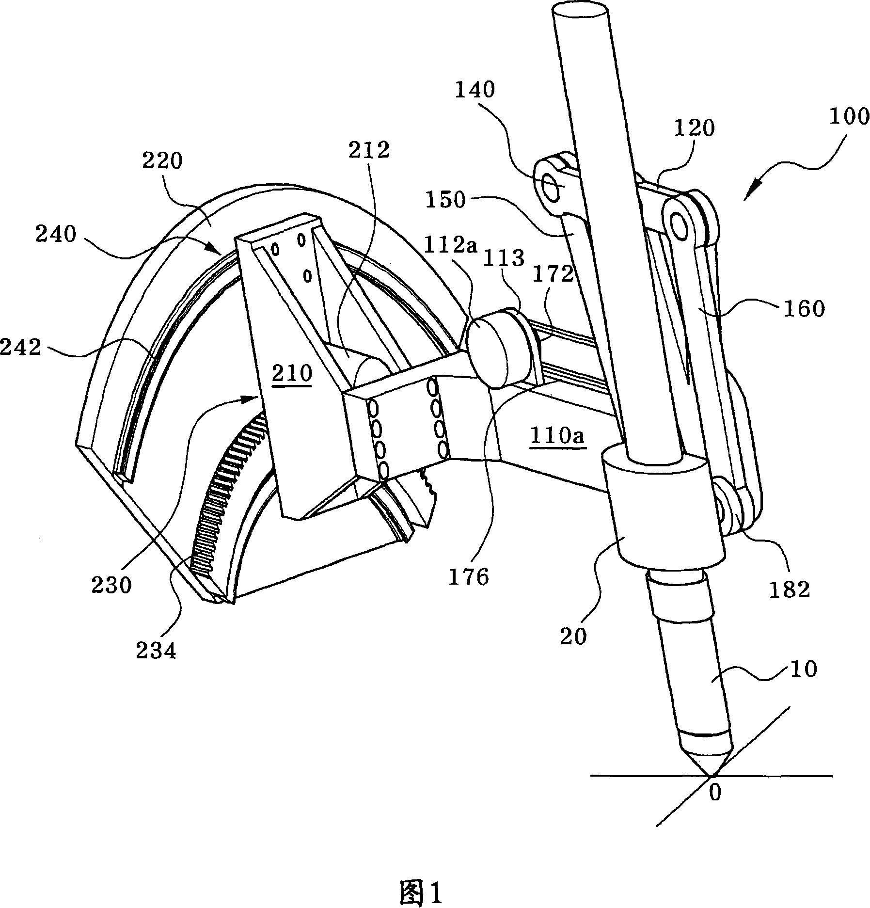
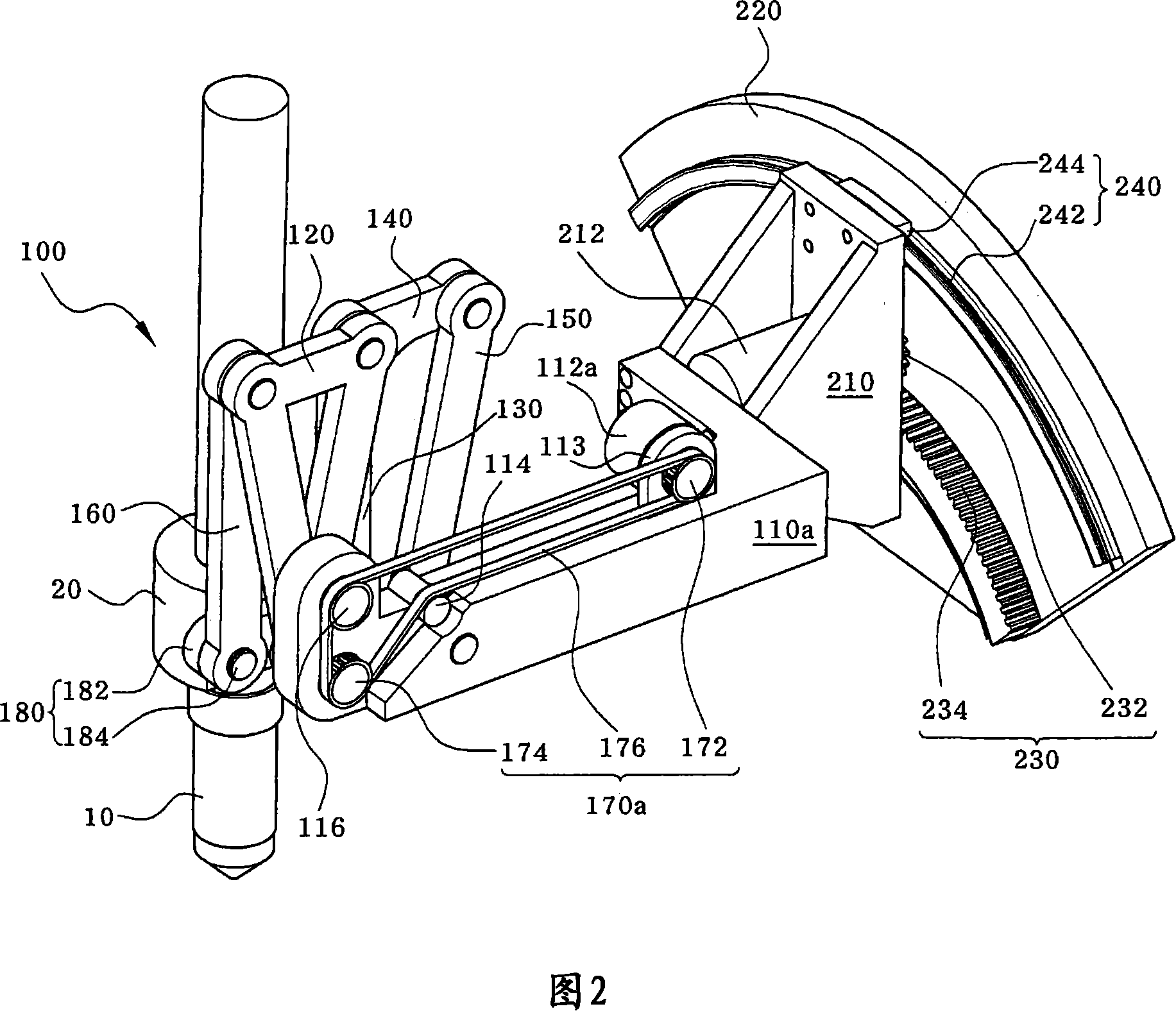
[0039] Fig. 1 is a perspective view of an angle adjustment device for a torch head according to an embodiment of the present invention. Fig. 2 is a rear perspective view showing the angle adjusting device of the torch head according to the embodiment of the present invention.

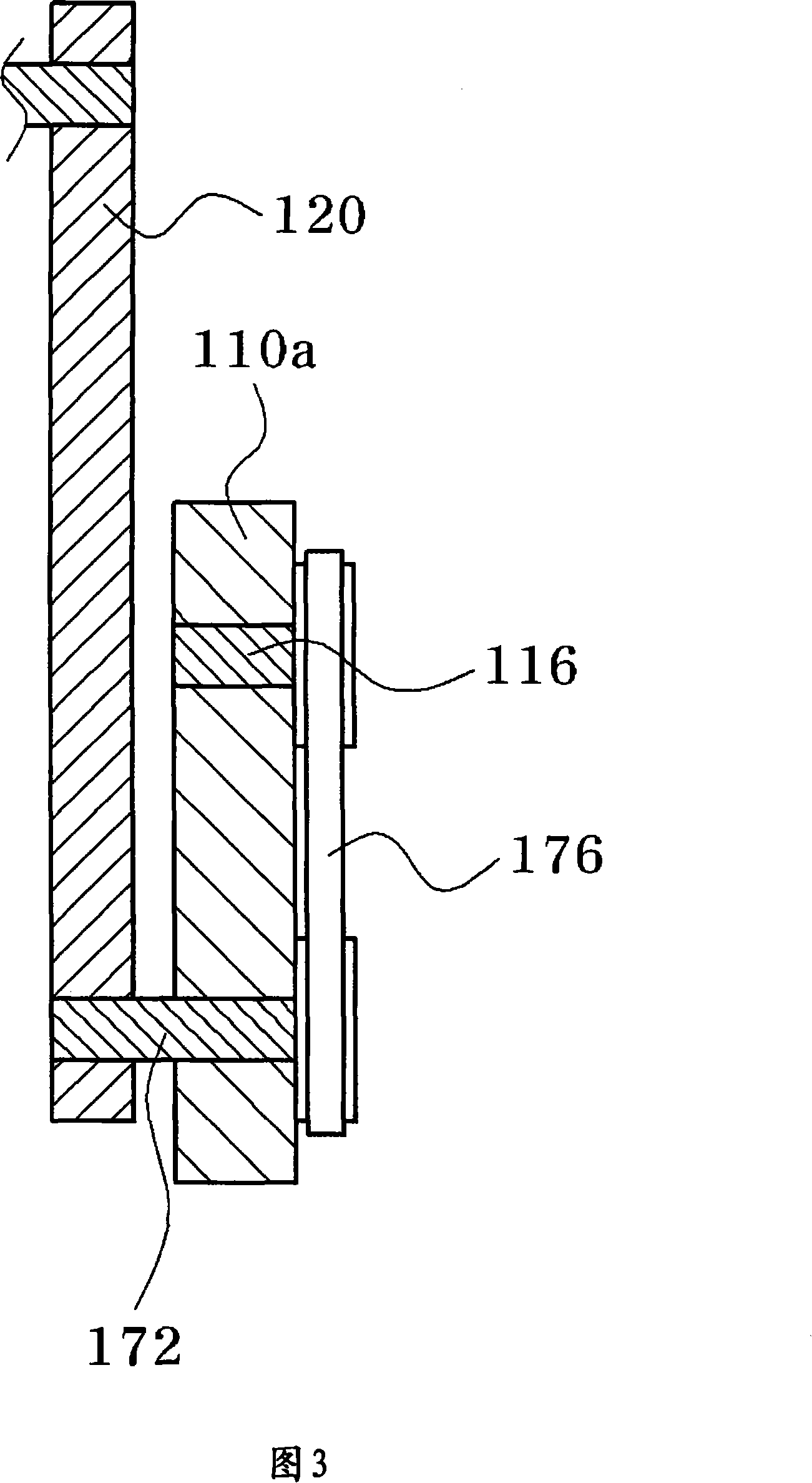
[0040] Moreover, FIG. 3 is a sectional view which shows the connection part of the link and the band member of the angle adjustment device of the torch head concerning one Example of this invention. Fig. 4 is an exploded perspective view showing a coupling structure of a torch head clamp and a link of the torch head angle adjusting device according to an embodiment of the present invention. Fig. 5 is a sectional view showing a guide structure of the angle adjusting device of the torch head according to the embodiment of the present invention.

[0041]In addition, FIGS. 6a and 6b are d...


PUM


Abstract

The present invention relates to an angle regulating device for a cutting torch head, which can make the cutting torch head gyre toward the pre and post direction by means of a circular-arc guiding piece, at the same time gyre toward the left and right direction by means of a connecting rod structure.

Description

technical field [0001] The present invention relates to an angle adjustment device of a cutting torch head, more specifically, it relates to using a link structure to make the cutting torch head turn to the left and right, and at the same time to use an arc-shaped guide to make the cutting torch head turn back and forth, thereby The utility model relates to an angle adjustment device of a cutting torch head which can rotate the cutting torch head in four directions with a simple structure. Background technique [0002] In the case of using the torch head of the plasma cutting torch to cut out graphics including straight lines and curves from steel plates or stainless steel plates and other materials to be cut, the moving path of the torch head is consistent with the outline of the target graphics, During the movement, the cutting torch head is driven to perform profiling cutting. [0003] A cutting device for performing profiling cutting, including: a monorail trolley trave...

Claims


Application Information

Patent Timeline
Patent Type & Authority Applications(China)
IPC IPC(8): B23K37/02B23K37/00
CPCB23K10/00B23K37/0211B23K37/0288B26F3/08G05B19/18
Inventor 金斗镐
Owner 金斗镐
Why Eureka
Try Eureka