Automobile clutch pedal self-adaptive regulating structure

An adaptive adjustment, clutch pedal technology, applied in the field of automobile transmission, can solve problems such as difficult pedal surface layout angles

Inactive Publication Date: 2010-09-08
CHERY AUTOMOBILE CO LTD
View PDF0 Cites 0 Cited by
  • Summary
  • Abstract
  • Description
  • Claims
  • Application Information

AI Technical Summary

Problems solved by technology

It is difficult to find a suitable pedal surface layout angle in the design to ensure the comfort requirements of all drivers

Method used


Image

  • Automobile clutch pedal self-adaptive regulating structure
  • Automobile clutch pedal self-adaptive regulating structure
  • Automobile clutch pedal self-adaptive regulating structure

Examples


Embodiment Construction

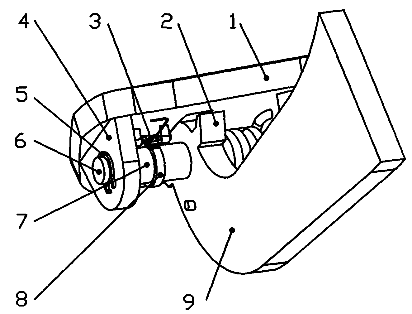
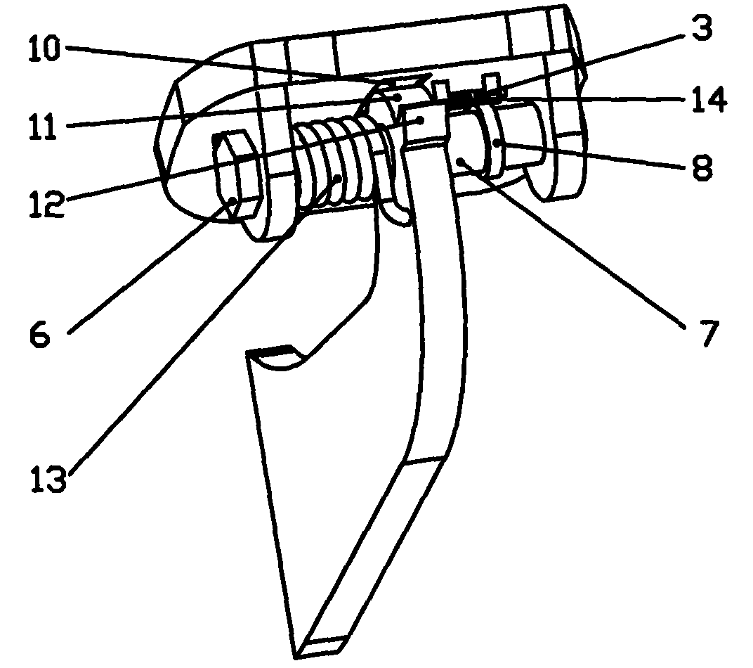
[0015] The adaptive adjustment structure of the automobile clutch pedal will be specifically described below in conjunction with the accompanying drawings.

[0016] As shown in Figures 1-3, the adaptive adjustment structure of the automobile clutch pedal includes a pedal surface 1, a pedal arm 9, a pedal shaft 6 and a return torsion spring, and the end of the pedal arm 9 has a semicircular boss 11 and Two step surfaces 2, 12, a guide groove 10 is formed at the position where the lower part of the pedal surface 1 is in contact with the pedal arm boss 11. When the pedal is depressed, the boss 11 at the end of the pedal arm 9 cooperates with the guide groove 10 , so that the pedal surface 1 can rotate relatively around the pedal rotating shaft 6 .

[0017] The step surface is divided into an upper limit step surface 2 and a lower limit step surface 12, which control the relative rotation angle of the pedal surface 1 to prevent the rotation angle from being too large and affecting...


PUM


Abstract

The adaptive regulation mechanism for clutch pedal of automobile includes one pedal plane, one pedal arm, one pedal rotation shaft and one reset torsion spring. The pedal arm has one semi-circular boss and two steps in the end, and the pedal plane has one guide slot in the lower part for contacting the boss in the pedal arm. After the pedal is treaded down, the boss in the pedal arm fits the guide slot, so that the pedal plane can rotate around the rotation shaft of the pedal and close to the foot of the driver comfortably.

Description

technical field [0001] The invention belongs to the field of automobile transmission, in particular to an adaptive structure of an automobile clutch pedal. Background technique [0002] When designing a complete vehicle, the layout of the clutch pedal must not only ensure the functional requirements of the clutch pedal, but also meet the requirements of human manipulation comfort, that is, the requirements of ergonomics. For the traditional clutch pedal mechanism, the pedal surface and the pedal arm are connected together by welding or bolts, and are fixed to each other. Once the design of the pedal mechanism is finalized, the angle between the pedal surface and the pedal arm is also fixed. In actual operation, since everyone has different requirements for the initial position of the pedal surface, it is difficult to ensure that the initial position meets the customary requirements of everyone during design. In the process of stepping on the clutch, due to the change of th...

Claims


Application Information

Patent Timeline
Patent Type & Authority Patents(China)
IPC IPC(8): B60K23/02
Inventor 刘亚辉向自生程振东
Owner CHERY AUTOMOBILE CO LTD
Why Eureka
Try Eureka