Water supply variable flow control system based on terminal comfort

A temperature control system and technology of the control system, applied in the field of air conditioning, can solve the problems of difficulty in meeting comfort requirements and energy waste, and achieve the effect of reasonable water supply flow and avoiding excessive water supply flow.

Active Publication Date: 2019-07-23
XINZHI ENERGY SYST CONTROL
View PDF6 Cites 0 Cited by
  • Summary
  • Abstract
  • Description
  • Claims
  • Application Information

AI Technical Summary

Problems solved by technology

[0005] The purpose of the present invention is to provide a water supply flow control system based on terminal comfort, which is used to solve the problem that it is difficult to meet the comfort requirements of all areas at all times by using the traditional area temperature control system for large systems with multi-area air conditioners. Or there is a problem of wasting energy

Method used


Image

  • Water supply variable flow control system based on terminal comfort
  • Water supply variable flow control system based on terminal comfort
  • Water supply variable flow control system based on terminal comfort

Examples


Embodiment 1

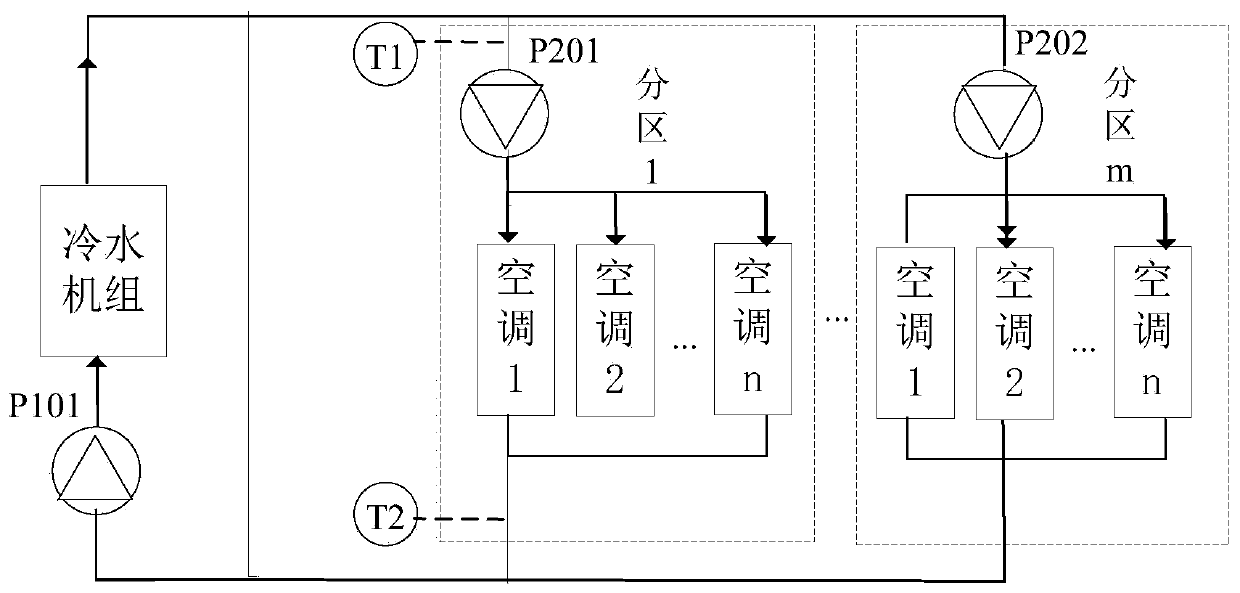
[0019] Such as figure 1 As shown, this embodiment provides a water supply variable flow control system based on terminal comfort, which is used in a central air-conditioning system. The central air-conditioning system is composed of chillers and distributed in multiple zones (that is, branch cooling areas, in figure 1 There are m partitions in the system), each partition covers multiple rooms or multiple sub-areas (for example, a larger partition in a large shopping mall, factory, etc. includes multiple sub-areas), each room or each sub-area At least one air conditioner is provided in the area. In the following description, a room is used as an example for illustration. According to different actual application scenarios, a sub-area may also be used instead of the room in this embodiment. The cold water unit is used to output cold water to each air conditioner, and the water output of the chiller unit is controlled by the total frequency conversion pump P101, and then the coo...

Embodiment 2

[0053] This embodiment provides a water supply variable flow control system based on terminal comfort. In this embodiment, the same parts as in Embodiment 1 are assigned the same reference numerals and their descriptions are omitted.

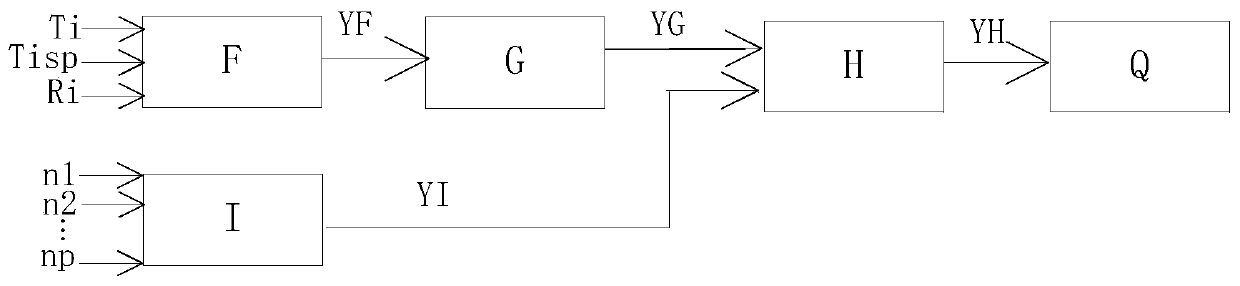
[0054] In this embodiment, the water supply variable flow control system includes: an over-temperature room ratio calculator F, an over-temperature room ratio controller G, a gain characteristic average calculator I, a gain controller H, a water supply frequency converter Q, and multiple temperature control system (not shown).

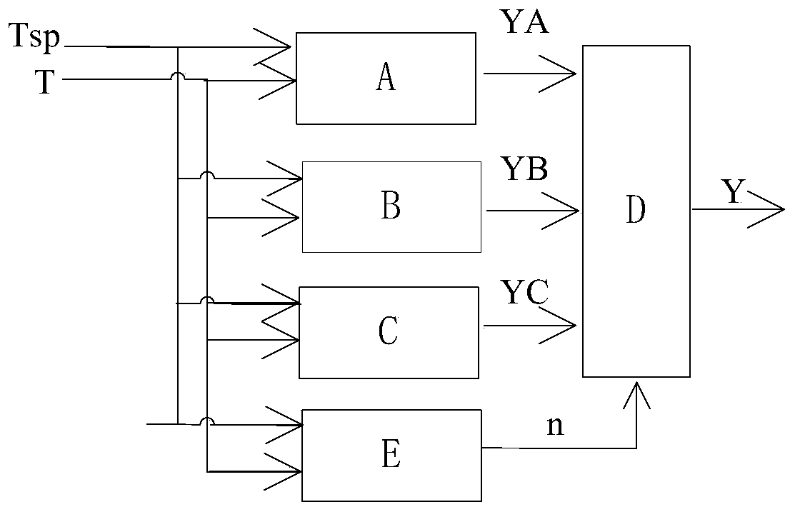
[0055] Such as Figure 4 As shown, the difference between this embodiment and Embodiment 1 is that the temperature control system in this embodiment includes: a gain self-tuner E, a gain calculator O, and a temperature controller P.

[0056] Regarding the above gain self-tuner E, the actual room temperature T and the preset room temperature Tsp are respectively used as the input of the gain self-tuner E, and the gain ch...


PUM


Abstract

The invention discloses a water supply variable flow control system based on end comfort, and relates to the technical field of air conditioners. The water supply variable flow control system is used for solving the problems that for an air conditioner large system including multiple areas, it is difficult to meet the requirements of all the areas in all time frames for comfort through a traditional area temperature control system, or energy is wasted. The water supply variable flow control system comprises an overtemperature room rate calculator used for controlling the overtemperature room rate, an overtemperature room rate controller, a plurality of temperature control systems used for controlling room temperature, a gain feature average calculator used for calculating the average value of all gain feature values to be used as a gain feature average value, a gain controller and a water supply frequency converter used for adjusting the water supply amount. The water supply variable flow control system based on end comfort is used for a central air conditioner.

Description

technical field [0001] The invention relates to the technical field of air conditioning, in particular to a water supply variable flow control system based on terminal comfort. Background technique [0002] In the existing air conditioning temperature control system. Adjust the water supply flow according to the temperature difference between the supply and return water, or adjust the outlet water temperature of the water supply unit according to the load, and then regulate the air conditioner temperature as a whole. Then adjust the speed of the fan according to the temperature deviation between the actual temperature of the room and the set temperature of the room, that is, adjust the wind speed of the fan to adjust the room temperature. [0003] Under normal conditions such as air conditioner design and type selection, reasonable HVAC construction, good weather, and normal room use, the above-mentioned existing air conditioner temperature control systems can meet the comf...

Claims


Application Information

Patent Timeline
Patent Type & Authority Patents(China)
IPC IPC(8): F24F11/89F24F11/64F24F110/10
CPCF24F11/30F24F11/89F24F2110/10
Inventor 肖珲宋国华牛世元王玉亮王志明
Owner XINZHI ENERGY SYST CONTROL
Why Eureka
Try Eureka