Elevator device

A technology for elevators and elevator shafts, which is used in elevators, transportation and packaging, elevators and other directions in buildings to achieve the effect of improving ride comfort and safety and improving installation workability.

Inactive Publication Date: 2010-05-19
MITSUBISHI ELECTRIC CORP
View PDF6 Cites 2 Cited by
  • Summary
  • Abstract
  • Description
  • Claims
  • Application Information

AI Technical Summary

Problems solved by technology

In this case, there is a problem that the support member on the wall side of the guide rail must be firm in order to bear the load applied to the guide rail.

Method used


Image

  • Elevator device
  • Elevator device
  • Elevator device

Examples


Embodiment 1

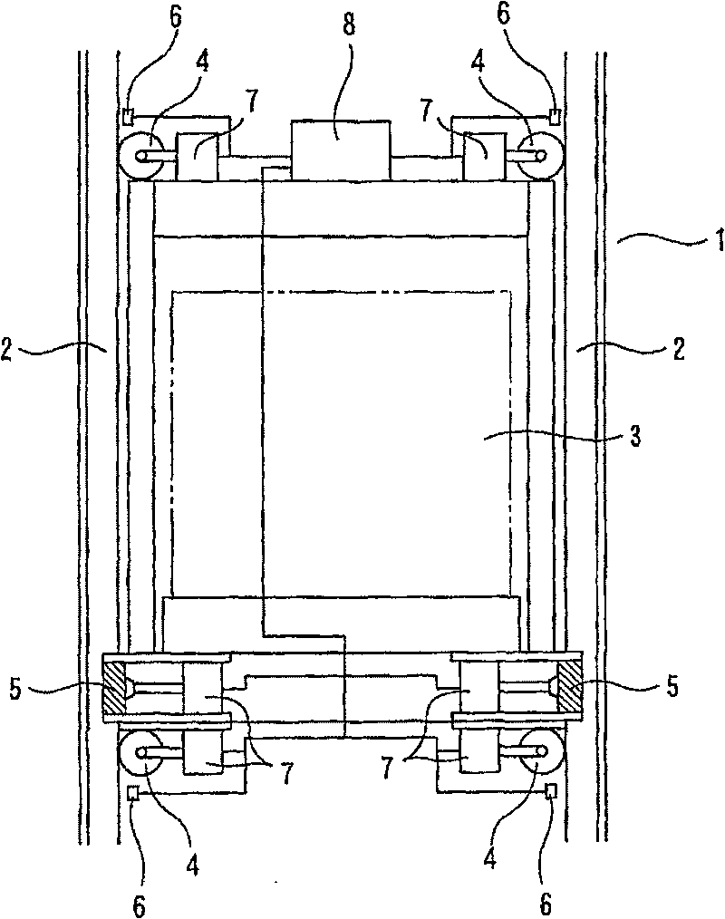
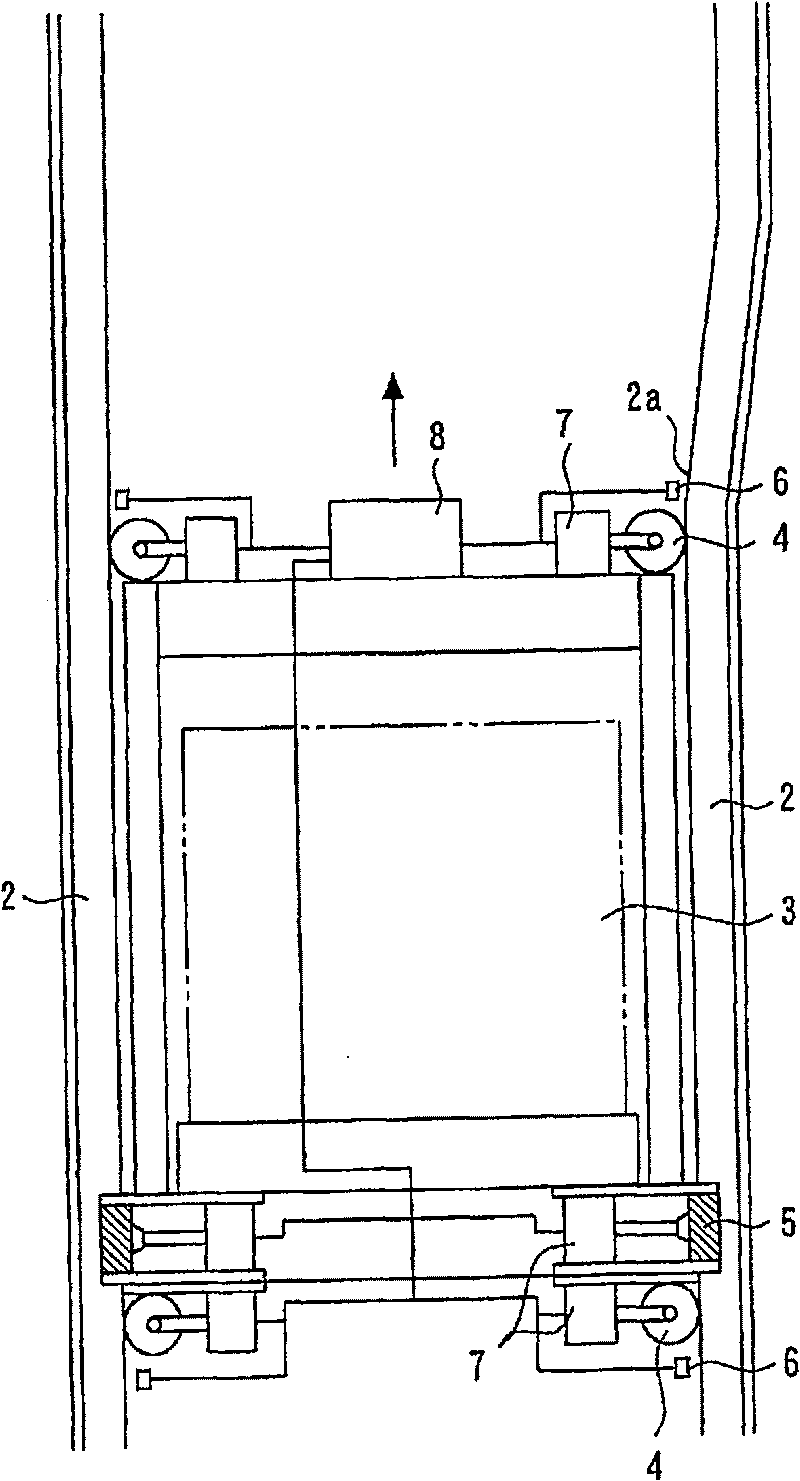
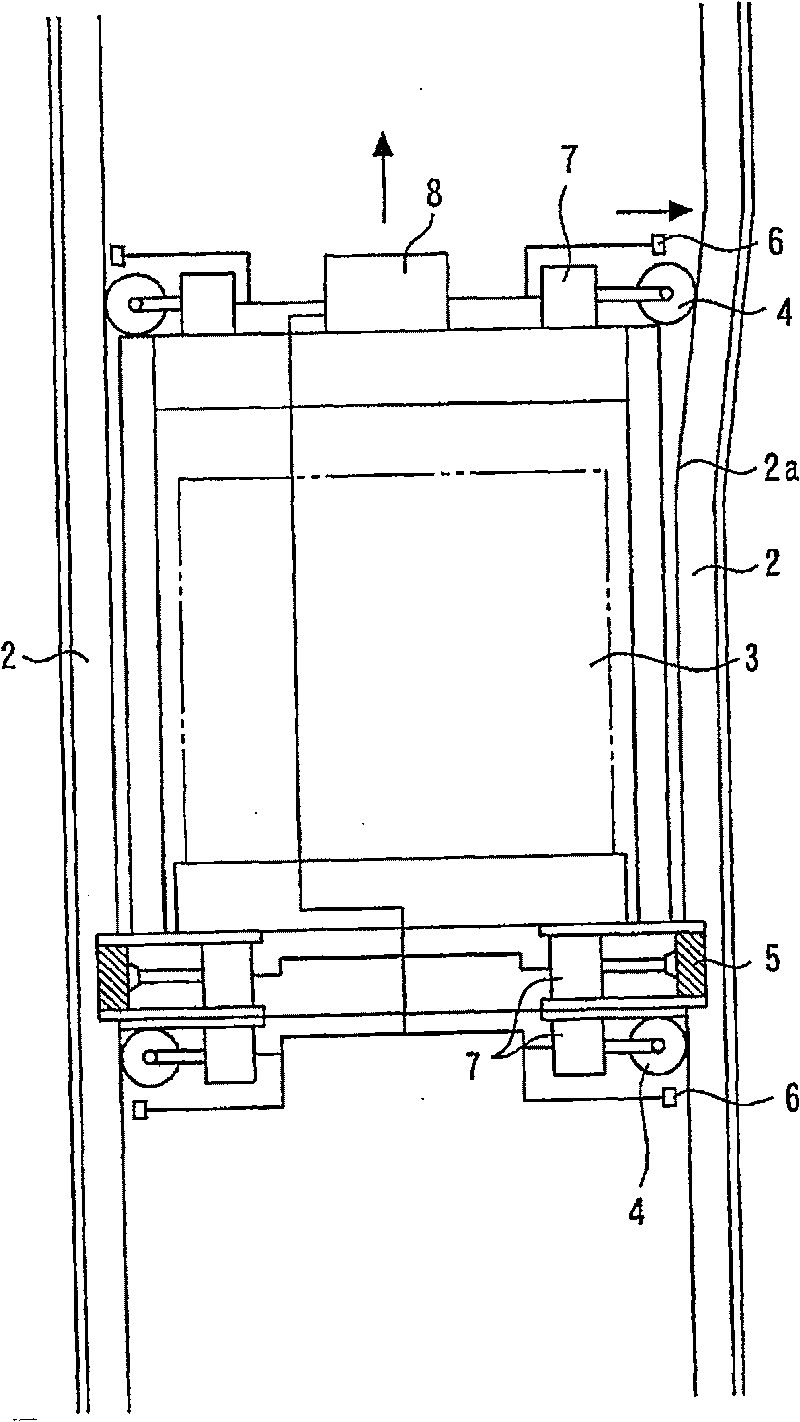
[0023] figure 1 It is a front view showing the elevator apparatus in Embodiment 1 of the present invention, figure 2 is the equivalent of an elevator device that represents a local change in the distance between guide rails figure 1 the picture, image 3 It is the equivalent of the state when the car is close to the position where the distance between the guide rails changes figure 2 the picture, Figure 4 It is a front view showing an elevator apparatus in which the distance between guide rails in Embodiment 1 of the present invention changes complicatedly, Figure 5 It is a front view showing the emergency stop device included in the elevator device according to Embodiment 1 of the present invention, Figure 6 It is equivalent to when the emergency stop device operates Figure 5 diagram.

[0024] In the figure, 1 represents the elevator shaft, and 2 represents a pair of left and right guide rails, which are respectively installed on the two side walls of the elevator...

Embodiment 2

[0041] In Example 1, the measuring device 6 is provided, but in Example 2, it is not necessary to provide it.

[0042] In the present embodiment 2, information such as the point where the distance between the left and right pair of guide rails 2 in the hoistway changes and the distance between the guide rails 2 is stored in the control device 8, and each driver 7 is operated based on this information. As a result, no measuring device is required, so that the construction and control of the elevator installation can be simplified.

Embodiment 3

[0044] Figure 7 It is a sectional view of a hoistway of an elevator apparatus according to Embodiment 3 of the present invention.

[0045] In the figure, 3a denotes a car of a self-propelled elevator. 1a denotes two elevator shafts of a self-propelled elevator, the distances between the guide rails of the elevator shafts are different, and the cars 3a move and rise and fall respectively in them. 1b represents a connecting passage connecting two elevator shafts 1a, and is a connecting means for moving the car 3a in the horizontal direction to and from between the two elevator shafts 1a. Here, the emergency stop device 5 adopts the structure described in the first embodiment.

[0046] According to the emergency stop device 5 provided in the elevator device constituted as described above, the same effect as that of Embodiment 1 can be obtained, and there is no need for a connection mechanism (upper tie rod, etc.) ), thus, there is no need to add a complicated structure for ma...


PUM


Abstract

An elevator device that can cope with a change in the distance between guide rails is provided in the present invention, in which ride comfort and safety of an elevator car are improved and in which workability in installation of the guide rails is enhanced. The elevator device has the car vertically moving in an elevator hoistway; the pair of guide rails arranged in the hoistway and whose relative distance is partially varied; a cage guide device capable of advancing to and retreating from a desired position in the horizontal direction relative to the car and constantly in contact with the guide rails while following the variation in the relative distance of the guide rails; and an emergency stop device provided at the car, capable of advancing to and retreating from a desired position inthe horizontal direction relative to the car, facing the guide rails with a constant distance from the rails while following the variation in the relative distance between the guide rails, and holding the guide rails when the car falls at overspeed, making an emergency stop of the car.

Description

technical field [0001] The present invention relates to an elevator installation having a guide device for an elevator car and an emergency stop device corresponding to changes in the distance between guide rails. Background technique [0002] In the conventional elevator apparatus, guide rails are provided in the hoistway, and the car is guided up and down in the hoistway by the guide rails, and a pair of emergency stop devices are installed on the car so as to face the guide rails. [0003] In addition, conventional elevator apparatuses have self-propelled elevators that move in a plurality of hoistways (for example, refer to Patent Documents 1 and 2). [0004] Patent Document 1 Japanese Patent Laid-Open No. 2000-185885 [0005] Patent Document 2 Japanese Patent Laid-Open No. 6-156939 [0006] In the conventional elevator apparatus, the guide rails installed on the wall surface of the hoistway to guide the raising and lowering of the car need to keep the distance between...

Claims


Application Information

Patent Timeline
Patent Type & Authority Patents(China)
IPC IPC(8): B66B7/04B66B5/22B66B7/02B66B9/16
CPCB66B5/22B66B7/046B66B7/042B66B9/003
Inventor 梶田昭成
Owner MITSUBISHI ELECTRIC CORP
Why Eureka
Try Eureka