Positioning method and device for flexble printed circuit wiring plate relative cramping means

A technology of flexible printed circuit and wiring board, which is applied in the direction of electrical connection formation of printed components, electrical components, electrical components, etc., and can solve problems such as poor pass rate, short circuit, insufficient solder, etc.

Inactive Publication Date: 2007-06-13
NIPPON MEKTRON LTD
View PDF2 Cites 2 Cited by
  • Summary
  • Abstract
  • Description
  • Claims
  • Application Information

AI Technical Summary

Problems solved by technology

[0002] Since thin film-like substrates such as flexible printed circuit boards are flexible, they cannot be directly set on a component mounting device for component loading.
In this way, the sheet-like substrate before being punched into a corresponding product is fixed on a dedicated transport jig formed of a metal plate, a synthetic resin plate, etc., and components are mounted. However, there are cases where unsuitable products are included in the same sheet. situation, it is necessary to check the unsuitable part
[0003] In the inspection of unsuitable products, it takes 0.2 to 0.5 seconds for each product, and it takes a long time to inspect multiple products, resulting in large losses
In addition, since parts are not mounted on inappropriate parts, suitable products with parts loaded and unsuitable products without parts are mixed on the same sheet, resulting in a decrease in the efficiency of the parts mounting line
[0004] If a plurality of flexible printed circuit boards cut into corresponding pieces are fixed on a transport jig, the workability of component mounting will be improved. However, since the substrate is soft and easily deformed, the positional accuracy of the corresponding product cannot be ensured, and there is printing of solder paste. In the case of misalignment, short circuits, insufficient solder, or unconnected solder are prone to occur in small parts and narrow pitch parts
In this way, in the loading of small components and narrow pitch components, the yield rate is deteriorated, and it is desired to have a method of fixing a plurality of flexible printed circuit boards cut into corresponding sheets with good precision, and performing component loading.

Method used


Image

  • Positioning method and device for flexble printed circuit wiring plate relative cramping means
  • Positioning method and device for flexble printed circuit wiring plate relative cramping means
  • Positioning method and device for flexble printed circuit wiring plate relative cramping means

Examples


Embodiment 1

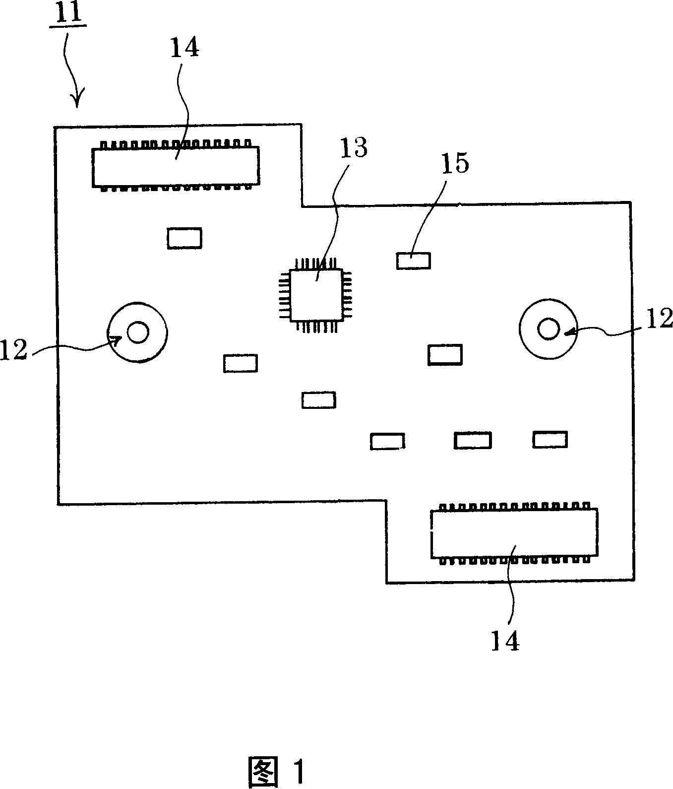
[0029] Fig. 1 is a conceptual diagram of a corresponding sheet-shaped flexible printed circuit wiring board (hereinafter referred to as FPC) 11 formed by stamping the outer shape. On the FPC 11 stamped into a corresponding sheet shape, reference positioning holes are provided at more than two positions. 12. In the illustrated example, a plurality of components including a semiconductor 13 and a connector 14 , a chip component 15 , etc. are mounted on a circuit pattern (not shown in the figure).

[0030] The above-mentioned reference positioning hole 12 constitutes a part of the second positioning mechanism 26 described later, but is provided through the base film, conductor and cover film constituting the FPC 11, and the hole diameters are different in the holes of the base film and the conductors and cover film.

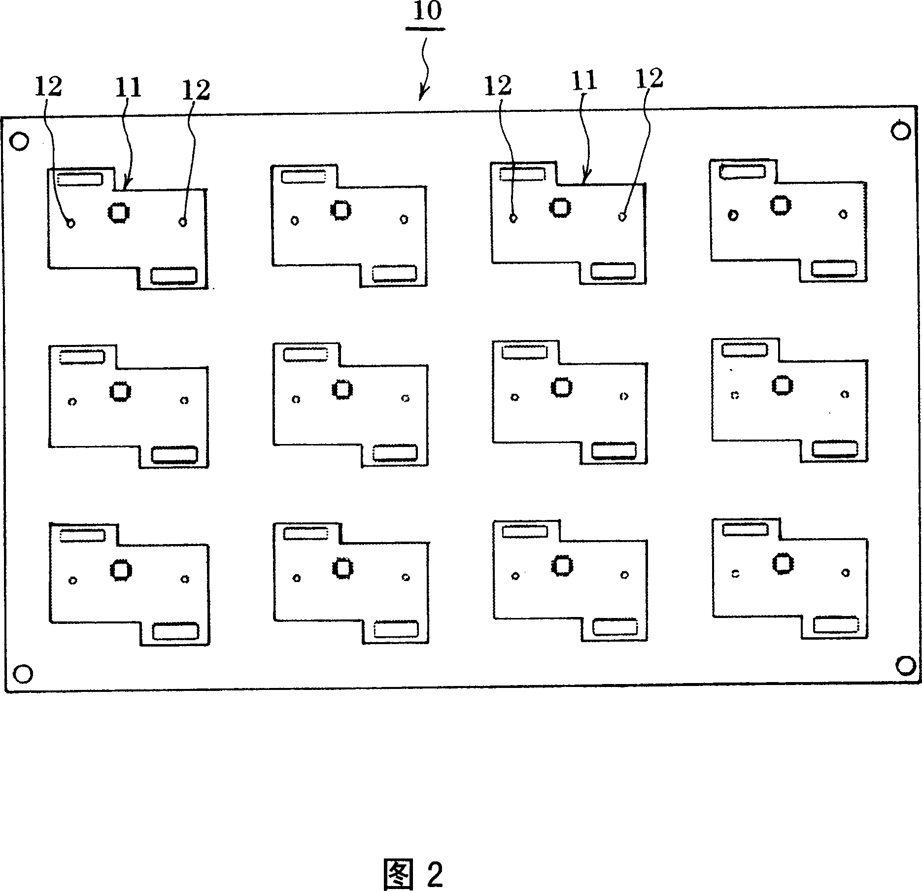
[0031] FIG. 2 shows an FPC sheet 10 on which a plurality of product FPCs 11 before press processing is placed. In this state, various holes (not shown) including t...


PUM


Abstract

The invention relates to a positioning method and a positioning apparatus for a transporting clamp for mounting a relative element of a flexible printed circuit wiring board. The subject of the invention is to provide a method and apparatus for positioning a plurality of flexible printed circuit wiring boards with a high precision when the flexible printed circuit wiring boards to be cut to corresponding sheets are fixed on the transporting clamp. The transporting clamp (22) is mounted on a cell of a mounting clamp (23) by a first position mechanism (24). The flexible printed circuit wiring board (FPC) (11) is held on a cell of the transporting clamp (22) mounted on the mounting clamp (23) in a tightly attached manner by a second positioning mechanism (26). Then the state of the FPC (11) is maintained, the transporting clamp (22) is removed from the mounting clamp (23), contact between the first position mechanism (24) and the second positioning mechanism (26) is released, the transporting clamp (22) holding the FPC (11) is transported to a component mounting process.

Description

technical field [0001] The present invention relates to a positioning method and a positioning device for a transport jig for mounting flexible printed circuit boards relative to components. In particular, the present invention relates to transporting a plurality of flexible printed circuit boards relative to each other in such a manner that they are held in close contact with good positional accuracy A positioning method and a positioning device for a fixture. Background technique [0002] Since thin film-like substrates such as flexible printed wiring boards are flexible, they cannot be directly set on a component mounting device to mount components. In this way, the sheet-like substrate before being punched into a corresponding product is fixed on a dedicated transport jig formed of a metal plate, a synthetic resin plate, etc., and components are mounted. However, there are cases where unsuitable products are included in the same sheet. If necessary, inspection of unsuit...

Claims


Application Information

Patent Timeline
IPC IPC(8): H05K13/04H05K3/40
Inventor 井上和夫
Owner NIPPON MEKTRON LTD
Why Eureka
Try Eureka