Clamp-On Type Ultrasonic Flowmeter

a technology of ultrasonic flowmeter and clamping device, which is applied in the direction of volume/mass flow measurement, measurement device, instruments, etc., can solve the problems of additive float on the surface, damping member may become too hard, and no desired results, etc., to achieve the effect of reducing damping performance and increasing the density of damping member

Active Publication Date: 2020-04-16
KEYENCE
View PDF0 Cites 2 Cited by
  • Summary
  • Abstract
  • Description
  • Claims
  • Application Information

AI Technical Summary

Benefits of technology

[0024]Based on the conventional design concept, the present inventor considered making the acoustic impedance of a damping member made with a cross-linked rubber approach or match the acoustic impedance of the metal piping. Then, various materials were added to the cross-linked rubber under the idea that it was only necessary to increase the density of the damping member in maki...

Problems solved by technology

However, no desired results were obtained.
When an additive is added to the cross-linked rubber, the damping member may become too hard or the additive may float o...

Method used


Image

  • Clamp-On Type Ultrasonic Flowmeter
  • Clamp-On Type Ultrasonic Flowmeter
  • Clamp-On Type Ultrasonic Flowmeter

Examples


embodiments

[0064]Preferred embodiments of the invention will be described below based on the attached drawings.

First Embodiment (FIG. 1 to FIG. 7)

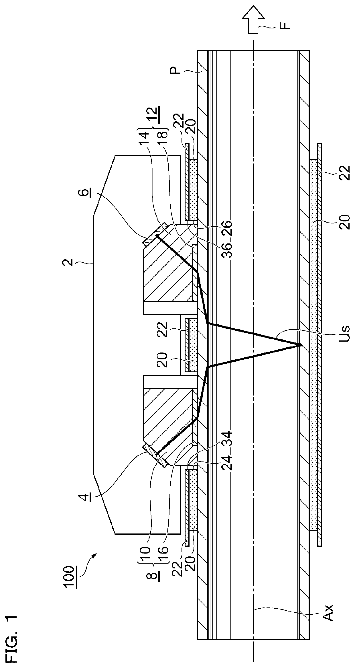
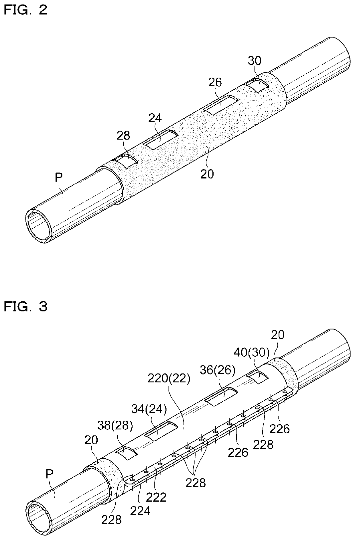
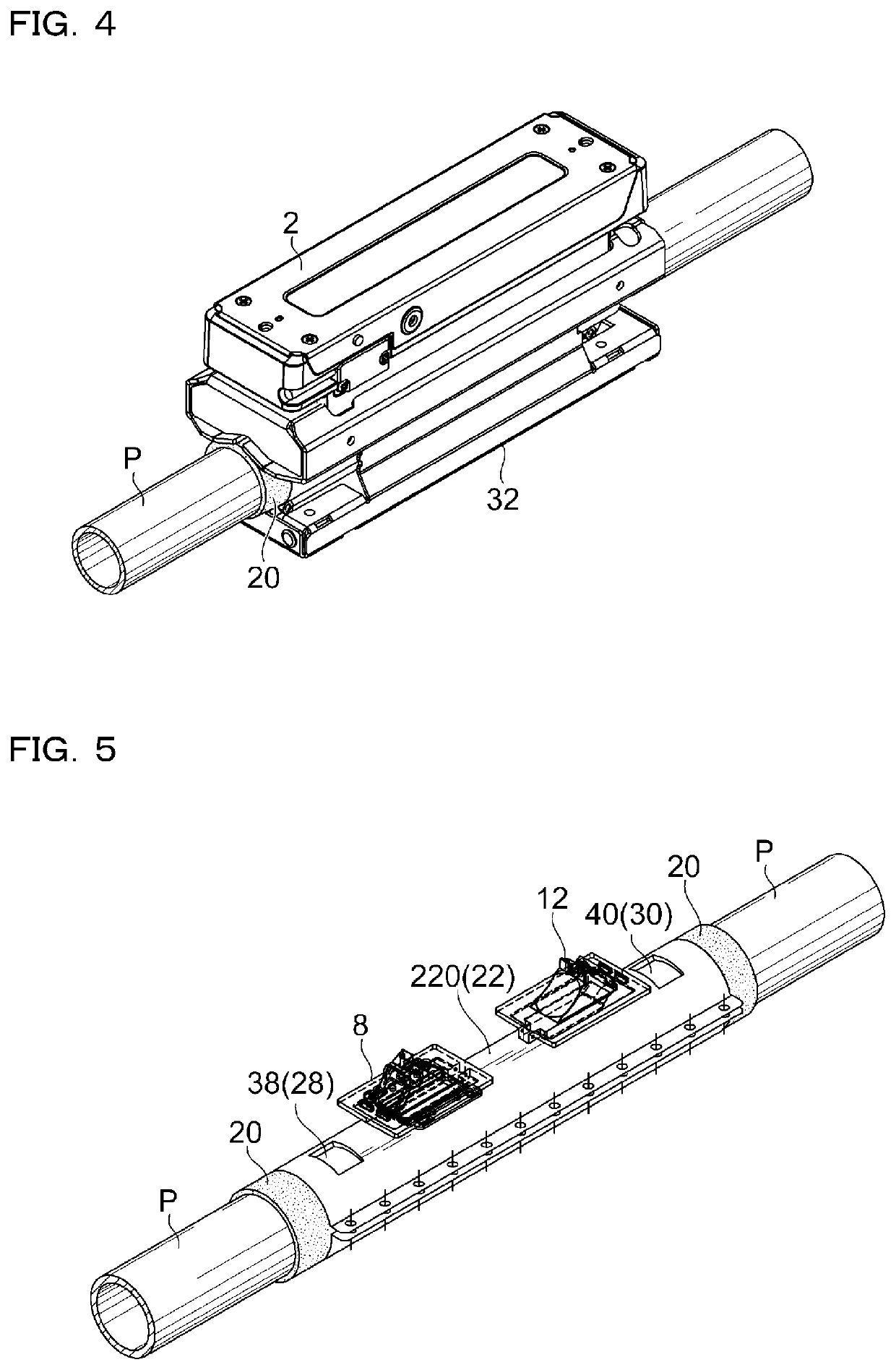
[0065]FIG. 1 to FIG. 7 are drawings relating to a clamp-on type ultrasonic flowmeter 100 of the first embodiment. A summary of the clamp-on type ultrasonic flowmeter 100 will be described with reference to FIG. 1. The flowmeter 100 has a flow sensor body 2 installed on piping P. A first ultrasonic device 4 and a second ultrasonic device 6 which transmit and receive an ultrasonic wave are incorporated in the flow sensor body 2. The first and second ultrasonic devices 4 and 6 typically include a piezoelectric device.

[0066]In the clamp-on type ultrasonic flowmeter 100, the first and second ultrasonic devices 4 and 6 are arranged on a mother line of the piping P apart from each other in a direction of an axis Ax of the piping P. That is, the ultrasonic flowmeter 100 of the first embodiment is a so-called clamp-on type flowmeter of a V-shape arrangement o...


PUM


Abstract

To improve installation work on piping for a clamp-on type ultrasonic flowmeter including a damping member. A damping member is provided in a state of being in contact with piping, and the damping member is a sheet-shaped molded article which has moderate flexibility and a predetermined thickness. In addition, the damping member has viscoelasticity and has adhesion and peelability to the metal piping. The damping member is fixed to the piping by a damping fixture surrounding an outer periphery of the damping member, and the damping member is pressed against the piping by the damping fixture. A flow sensor body is fixed on the damping member.

Description

CROSS-REFERENCE TO RELATED APPLICATIONS[0001]The present application claims foreign priority based on Japanese Patent Application No. 2018-192967, filed Oct. 11, 2018, the contents of which is incorporated herein by reference.BACKGROUND OF THE INVENTION1. Field of the Invention[0002]The present invention relates to a flowmeter which generally measures a flow velocity and a flow rate of a fluid flowing in piping using an ultrasonic wave, and more specifically to a clamp-on type ultrasonic flowmeter which is installed post-fitting on piping.2. Description of Related Art[0003]There has been known a measuring instrument using an ultrasonic wave to measure a flow velocity and a flow rate of a fluid flowing in piping. This kind of measuring instrument is called an “ultrasonic flowmeter”.[0004]A principle of the ultrasonic flowmeter basically utilizes, when an ultrasonic wave is made obliquely crossing a fluid flowing in piping (a fluid to be measured), a time difference between an outward...

Claims


Application Information

Patent Timeline
IPC IPC(8): G01F1/66
CPCG01F1/662G01F1/667
Inventor KAWAGUCHI, YASUNORI
Owner KEYENCE
Why Eureka
Try Eureka