Eureka AIR delivers breakthrough ideas for toughest innovation challenges, trusted by R&D personnel around the world.

Telescopic tube for electric vacuum cleaner

A technology of vacuum cleaners and telescopic tubes, applied in the direction of suction hoses, suction nozzles, etc., can solve the problem of easy damage to the joints, and achieve the effect of preventing the disconnection of the joints

Inactive Publication Date: 2004-07-28
SANYO ELECTRIC CO LTD
View PDF0 Cites 2 Cited by
  • Summary
  • Abstract
  • Description
  • Claims
  • Application Information

AI Technical Summary

Problems solved by technology

[0004] However, in this conventional device, when the wiring mechanism expands and contracts, a force is applied to the connecting portion between both ends of the wiring mechanism and the power lead, and there is a problem that the connecting portion is easily damaged.

Method used


Image

  • Telescopic tube for electric vacuum cleaner
  • Telescopic tube for electric vacuum cleaner
  • Telescopic tube for electric vacuum cleaner

Examples


Embodiment Construction

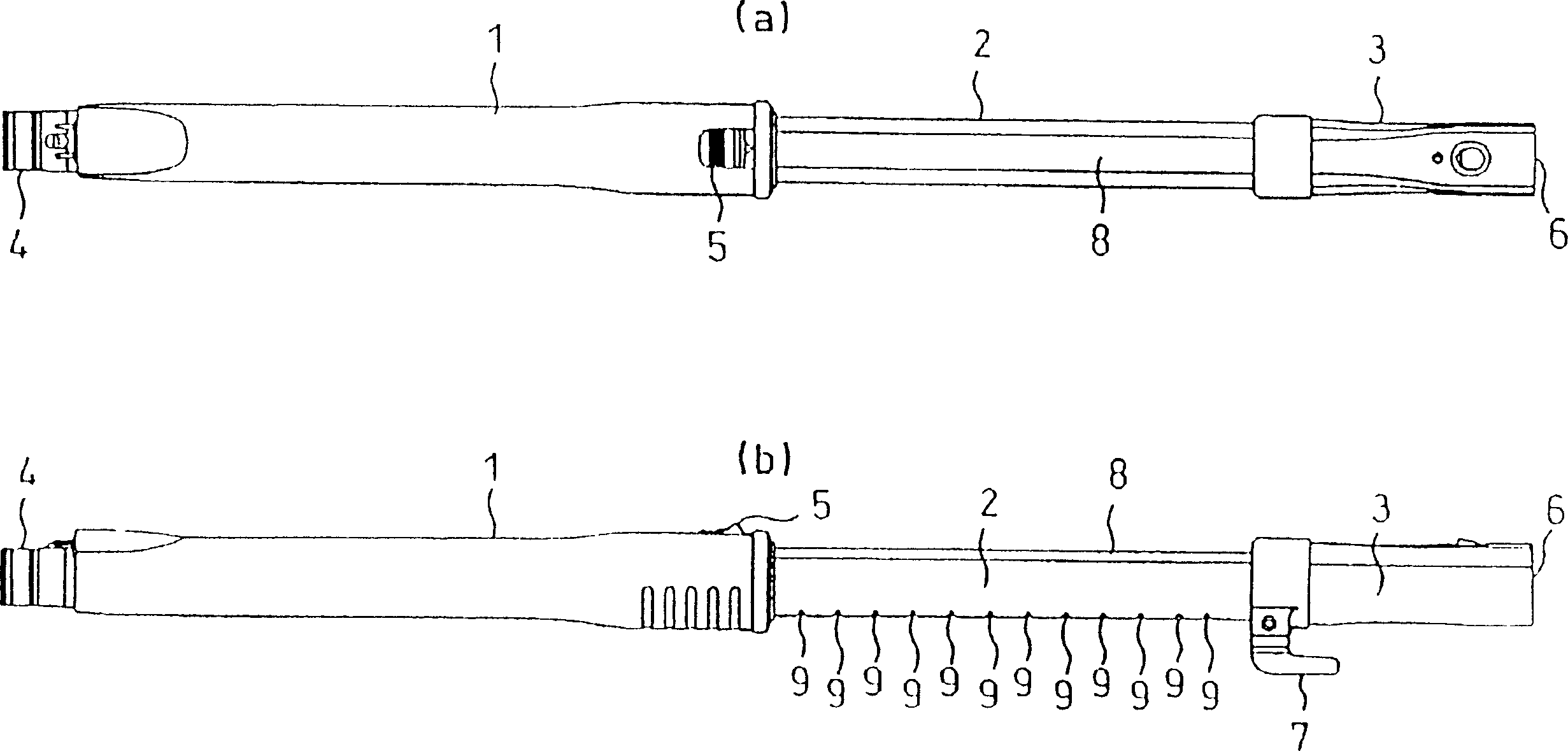
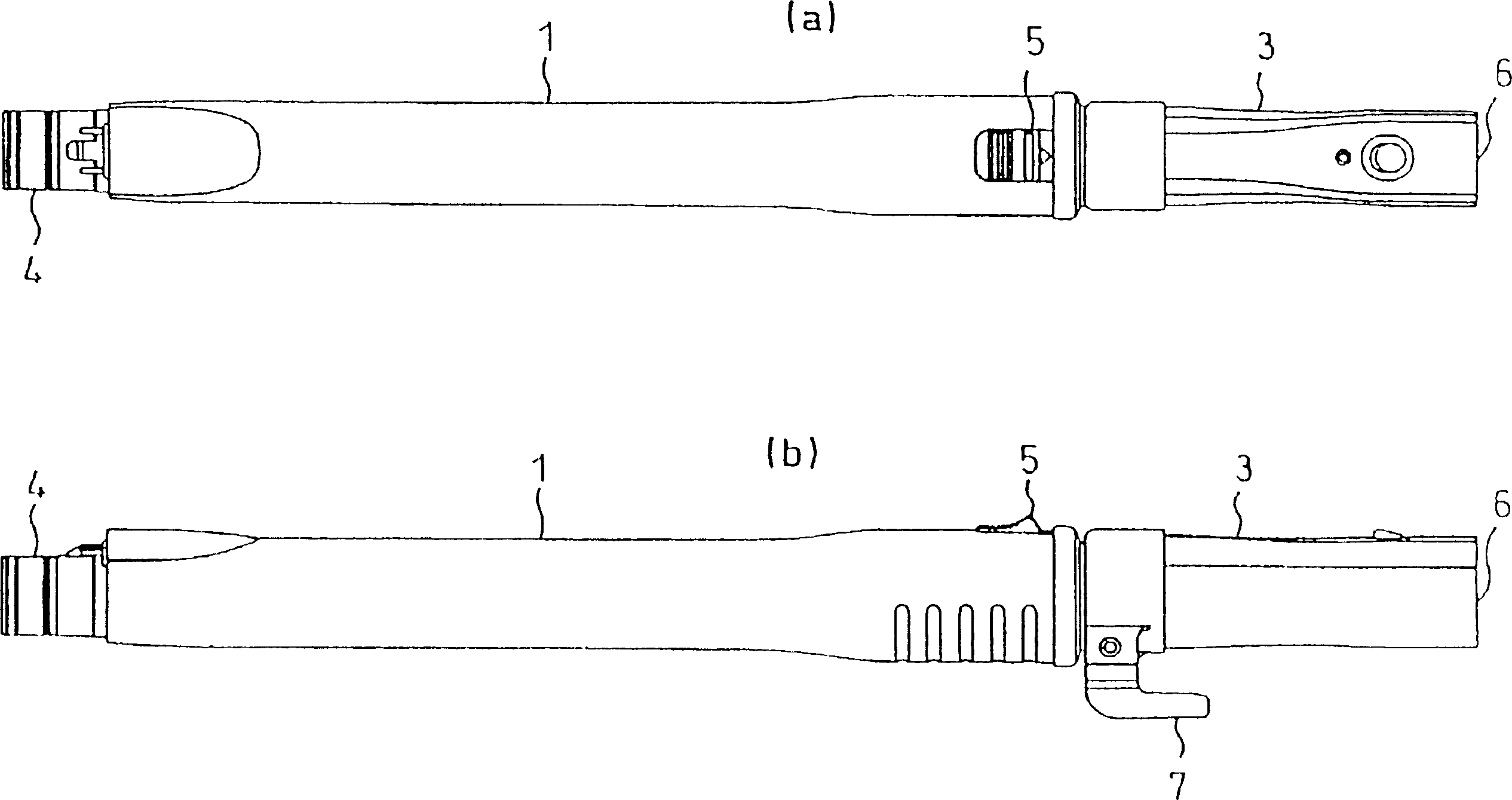
[0044] Below, refer to the attached figure 1 The embodiment of the present invention will be described.

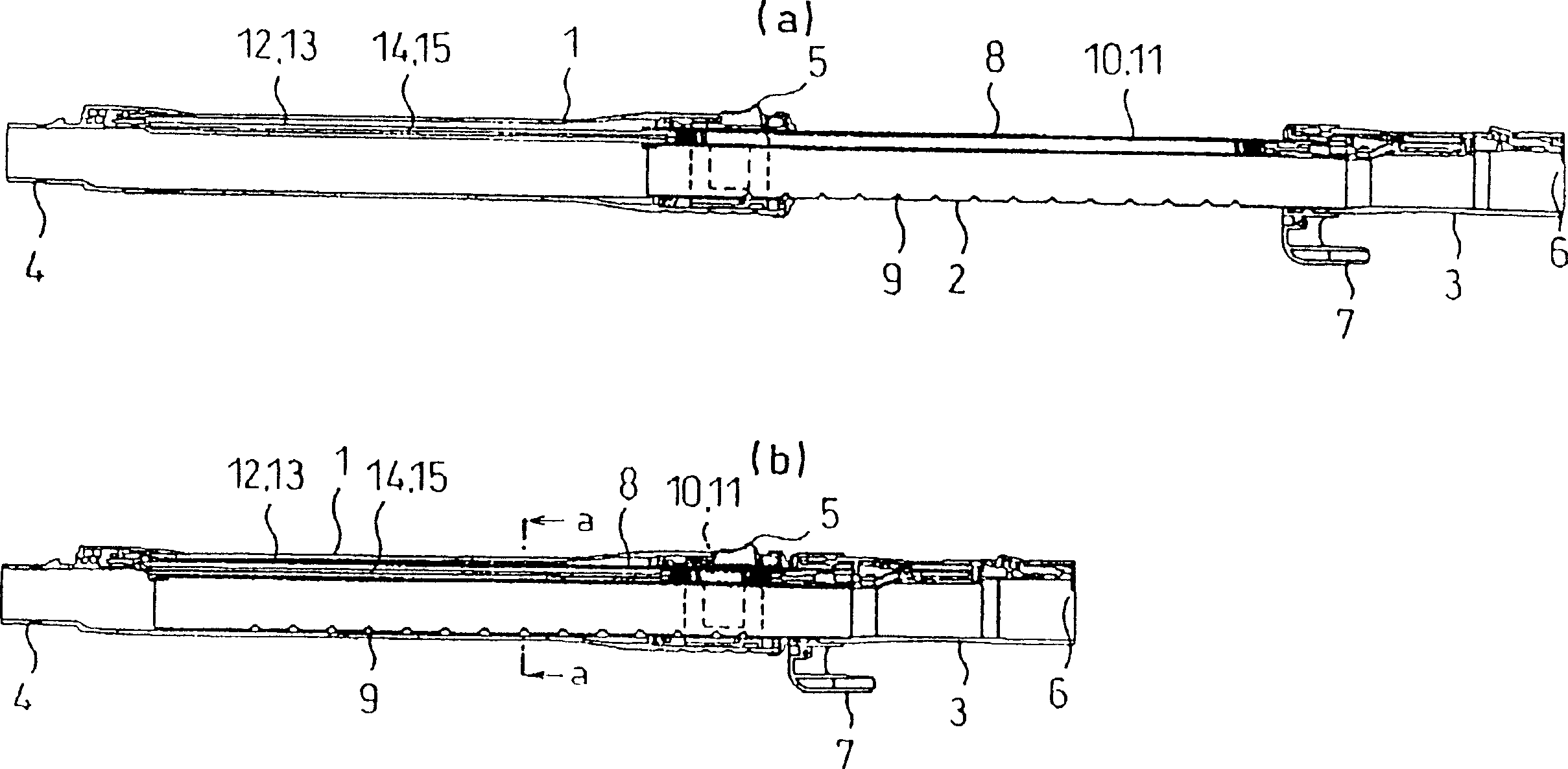
[0045] figure 1 (a), (b) and figure 2 (a) and (b) show the telescopic tube of an electric vacuum cleaner according to an embodiment of the present invention.

[0046] The telescopic tube roughly includes an outer tube 1 connected to the main body (not shown) of the electric vacuum cleaner, and a connecting member 3 connected to the electric brush (not shown) of the suction device, and is connected to the outer tube 1 The inner tube 2 of the connecting member 3; the inner tube 2 is in a state where the outer tube 1 can enter and exit, and is fixed at an appropriate protruding position.

[0047] The outer tube 1 is provided with a connecting portion 4 for connecting to the main body side, and an operation portion 5 for understanding the fitting state of the outer tube 1 and the inner tube 2, and a connecting member 3 is provided for connecting to the electric brush side The ...


PUM


Abstract

To prevent the breaking of expansion springs by providing a first and a second sleeves, which are stored in an inner and outer pipe, respectively and slidably inserted therein mutually in a wiring mechanism, and storing the expansion spring connected to a terminal of one pipe end. An expansion pipe is formed of an outer pipe connected to a vacuum cleaner main body side, a coupling member connected to a power brush side of a suction means, and an inner pipe 2 for connecting them to each other. A storing part 8 for storing a wiring mechanism including a pair of expansion springs 10, 11 which feed power supply to the power brush is formed in the inner pipe 2. The respective expansion springs 10, 11 have the diameter smaller than the internal diameter of a cylindrical part provided in a sleeve 16, which is inserted in the storing part 8, have the both ends formed into tapered states, and have lead wires 14, 15 connected to the respective ends. The central parts of the expansion springs 10, 11 are formed into the large diameters matching the internal diameters of the cylindrical parts of the sleeves 12, 13 so that the spring load can be reduced.

Description

【Technical Field】 [0001] The present invention relates to a telescopic tube of an electric vacuum cleaner which is interposed between a tube installation port of an electric vacuum cleaner body and a power brush for suction. 【Background technique】 [0002] As is well known in the prior art, as a telescopic tube of an electric vacuum cleaner equipped with an electric brush for suction, an inner tube is freely provided in and out of the outer tube, and the length of the inner tube protruding from the outer tube is adjusted to lock the telescopic tube. [0003] In this conventional device, the wiring mechanism for the power supply used to drive the electric brush can be constructed using a retractable spring whose length can be changed as the inner tube goes in and out of the outer tube. [0004] However, in such a conventional device, when the wiring mechanism expands and contracts, a force is applied to the connecting portion between the both ends of the wiring mechanism and the p...

Claims


Application Information

Patent Timeline
Patent Type & Authority Applications(China)
IPC IPC(8): A47L9/24A47L9/02
Inventor 吉见和好米田勳
Owner SANYO ELECTRIC CO LTD
Why Eureka
Eureka Blog
Learn More