Optical disc device

An optical disc device and optical disc technology are applied in the direction of planar recording carrier equipment, driving/moving recording head, poor vibration/sound insulation/absorption, etc., which can solve the problems of large characteristic changes and increased manufacturing costs, and achieve vibration suppression, The effect of reducing the number of parts and reducing the manufacturing cost

Inactive Publication Date: 2008-01-09
YAMAUCHI CORP
View PDF1 Cites 0 Cited by
  • Summary
  • Abstract
  • Description
  • Claims
  • Application Information

AI Technical Summary

Problems solved by technology

[0007] The optical disc device 1 having the above-mentioned structure needs to be equipped with a dynamic damping mechanism or a compensating motor in order to suppress vibration, which is one of the causes of increased manufacturing cost.
In addition, as shown in FIG. 9, when the horizontal frame 4 is supported on the casing 2 from the vertical direction, there is a problem that the characteristics change due to the change in the posture of the optical disc device 1 is large.

Method used


Image

  • Optical disc device
  • Optical disc device
  • Optical disc device

Examples


Embodiment Construction

[0027] An optical disc device 21 according to an embodiment of the present invention will be described with reference to FIGS. 1 to 3 .

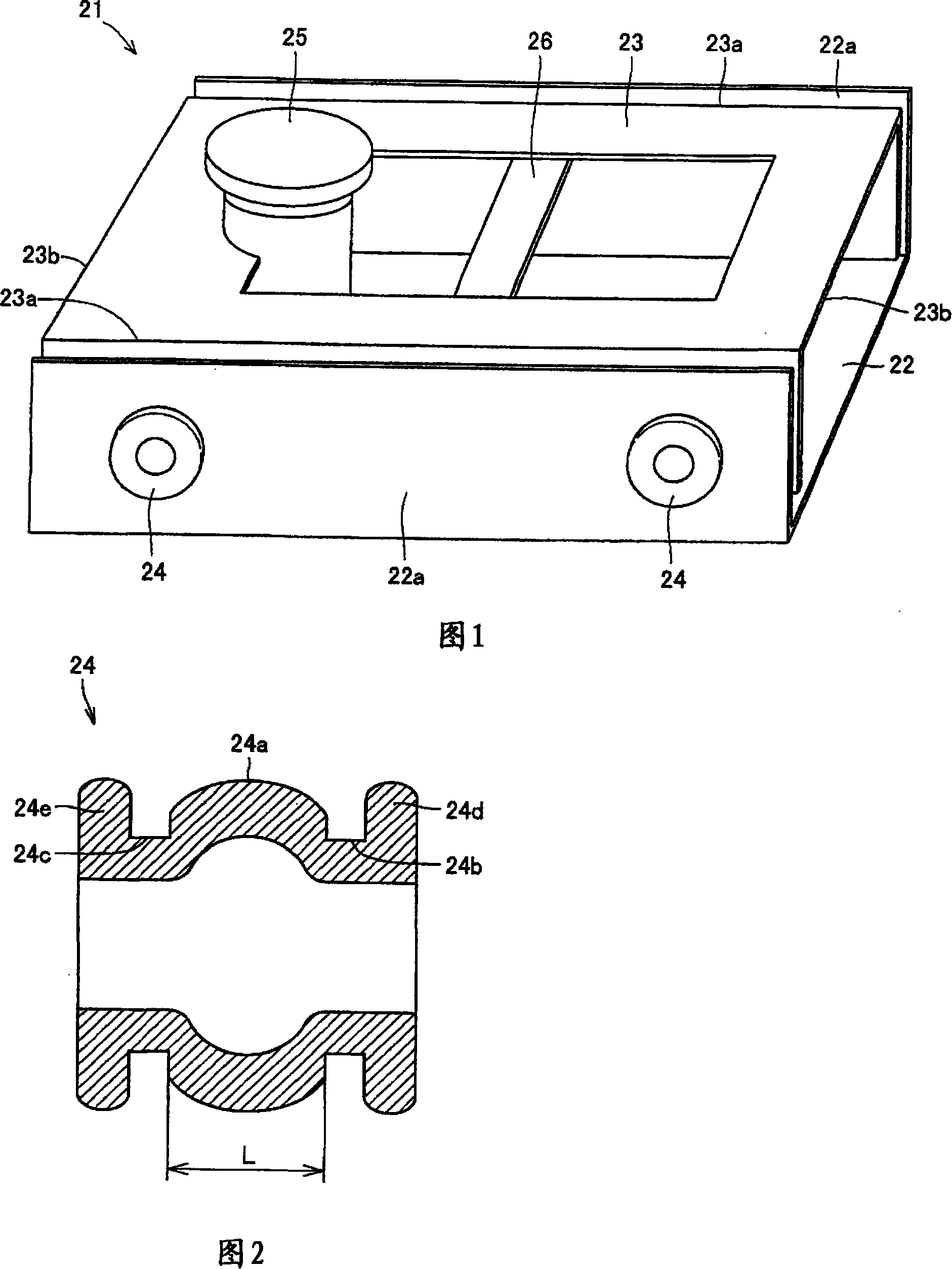
[0028] FIG. 1 is a perspective view of an optical disc device 21 . The optical disc device 21 includes: a casing 22 having a side wall 22 a ; a horizontal frame 23 ; and an elastic member 24 supporting the horizontal frame 23 on the casing 22 .

[0029] The horizontal frame 23 is rectangular including a pair of long sides 23a and a pair of short sides 23b, and supports a spindle motor 25 and an optical sensor holder 26 for driving an optical disk. The horizontal frame 23 is attached to the side wall 22a of the housing 22 from the horizontal direction by means of four elastic members 24 arranged at two places on each of the pair of long sides 23a.

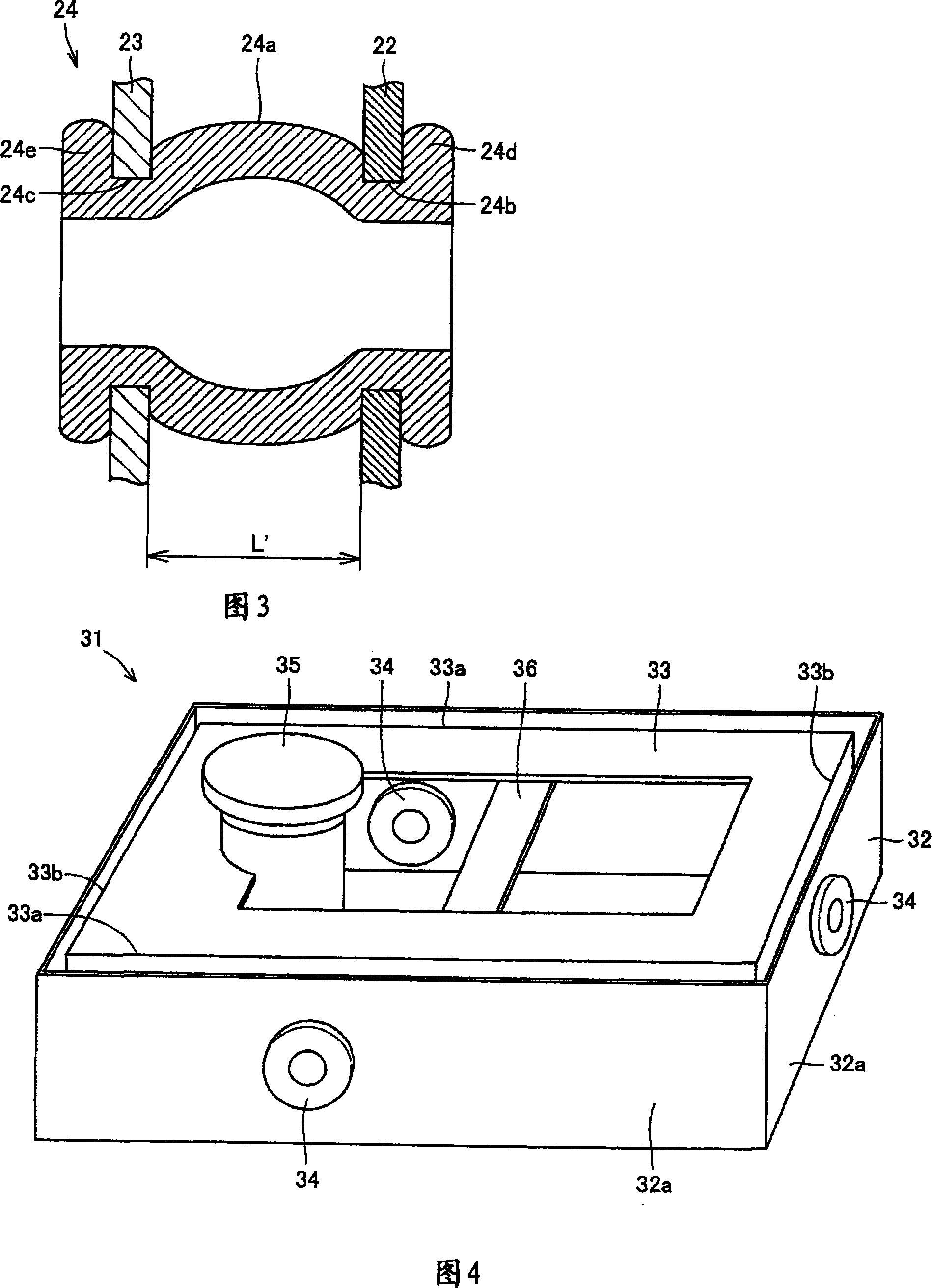
[0030] 2 and 3 are diagrams showing states of the elastic member 24 before and after installation. With reference to Fig. 2, elastic member 24 is cylindrical shape, and it comprises the cylindri...


PUM


Abstract

An optical disk device (21) has a housing (22), a traverse chassis (23) for supporting a motor that drives an optical disk, an elastic member (24) for supporting the traverse chassis (23) from the direction in horizontal to the housing (22), a spindle motor (25), and an optical-pickup holder (26). The elastic member (24) is installed between the housing (22) and the traverse chassis (23) such that it is longer than its natural length by an amount corresponding to an elongation ratio L.

Description

technical field [0001] The present invention relates to an optical disc device mounted in a personal computer, a DVD recorder, or the like. Background technique [0002] As a conventional optical disc device, for example, an optical disc device 1 shown in FIG. 9 is known. This optical disc device 1 is provided with: a horizontal frame 4 and a dynamic shock absorber 5 supported by an elastic member 3 on the bottom of a casing 2 (only a part thereof is shown in FIG. 9 ); Spindle motor 6 and optical sensor holder 7 . [0003] Elastic member 3 is as shown in Figure 10, has the cylindrical part of constriction part 3a, 3b, 3c in 3 positions, and casing 2 is installed in constriction part 3a place respectively, and transverse machine is installed in constriction part 3b place. The frame 4 is installed with a dynamic shock absorber 5 at the constricted portion 3c. [0004] In the optical disc device 1 configured as described above, the disc (not shown) mounted on the spindle mot...

Claims


Application Information

Patent Timeline
IPC IPC(8): G11B33/08G11B25/04
CPCG11B33/12G11B21/02G11B33/08
Inventor 小川良
Owner YAMAUCHI CORP
Why Eureka
Try Eureka