Water closet water-saving, washing and water supplying apparatus

A flush toilet and drainage device technology, applied in the field of sanitary ware, can solve the problems of no water in the water tank, complex structure, increase the manufacturing cost and sales price of the flush toilet, and achieve the effect of saving tap water

Inactive Publication Date: 2008-01-16
吴思思
View PDF1 Cites 4 Cited by
  • Summary
  • Abstract
  • Description
  • Claims
  • Application Information

AI Technical Summary

Problems solved by technology

[0002] In the prior art, there are usually two kinds of water-saving flushing water supply devices for toilets that use secondary use of daily water: one is to directly connect the single water storage tank of the original toilet with the tap water pipe and the waste water inlet pipe at the same time, but because the waste water inlet pipe The water source has great uncertainty, and a water injection switch must be set on the water pipe. When there is no water source or insufficient water in the waste water inlet pipe, there will be no water or less water in the water tank, and the water pipe needs to be turned on when flushing the toilet. It takes a certain amount of time to fill the water tank with water, and the toilet cannot be flushed in time, and the water filling switch needs to be turned off after the tap water fills the water tank, so as to free up waste water storage space for the water tank after flushing, which is very troublesome to use
The other is a double-tank flush toilet, such as the Chinese patent 200610029208.1 double-tank flush toilet, which is characterized in that the water tank is divided into a tap water tank and a waste water tank by a partition, and mutually independent flushing and discharging water tanks are respectively provided in the tap water tank and the waste water tank. device, which not only has a complex structure and makes troubles, but also greatly increases the manufacturing cost and sales price of the flush toilet

Method used


Image

  • Water closet water-saving, washing and water supplying apparatus

Examples


Embodiment Construction

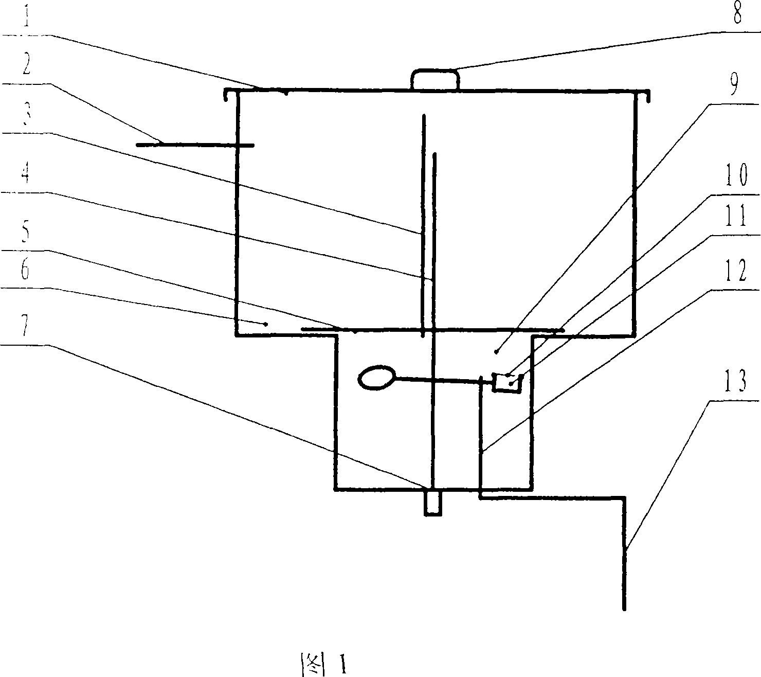
[0009] As shown in Figure 1: The water-saving flushing and water supply device for the flush toilet of the present invention is mainly composed of a water storage tank 1, a drainage device 7 located in the water tank and installed on the drain port of the water storage tank, and a tap water inlet with a float valve structure installed at the bottom of the water storage tank 1. The water control device 12, the flushing control button 8 installed on the top or side of the water storage tank 1, the overflow pipe 4 connected with the outlet, the waste water inlet pipe 2, the tap water inlet pipe 13 are composed; it is characterized by: the water tank layered partition 5 Separate the water storage tank 1 into an upper grid water tank 6 and a lower grid water tank 9. The upper grid water tank 6 is greater than or equal to the lower grid water tank 9, and the water tank layered partition 5 is movable with the water storage tank 1 and has a clearance fit; the tap water control device 12 i...


PUM


Abstract

A water-saving flush water supply device for toilets is provided, which mainly comprises a water storage tank (1), a water drainage device (7) positioned at the site of a drainage port inside the water storage tank, a tap water inlet controller (12) arranged at the bottom of the water storage tank (1) and having a floating-ball valve structure, a flushing water control button (8) arranged on the top or the side wall of the water storage tank (1), and an overflow pipe (4) communicated with the drainage port. The device is characterized in that the water storage tank (1) is divided by a water tank partition (5) to an upper water portion (6) and a lower water portion (9), the water tank partition (5) being movably engaged with the water storage tank (1); the tap water inlet controller (12) is arranged inside the lower water portion (9); an air inlet pipe (3) is arranged on the water tank partition (5) in a way that the upper end thereof is positioned above the overflow pipe (4) and the lower end thereof is positioned inside the lower water portion (9). The invention has the advantages of large storage of waste water from bathing room, reduced consumption of tap water, multiple toilet-flushing effect, and good water-saving effect.

Description

Technical field [0001] The invention relates to a sanitary ware, in particular to a water-saving flushing and water-supplying device for a flush toilet that adopts secondary use of daily water. Background technique [0002] In the prior art, there are usually two types of flushing and water-saving devices for flushing toilets that use the secondary use of daily water: one is to directly connect the single water storage tank of the original toilet with the tap water pipe and the waste water inlet pipe at the same time, but due to the waste water inlet pipe The water source of the company has great uncertainty, and a water injection switch must be set on the tap water pipe. When there is no water source or insufficient water source in the wastewater inlet pipe, there will be no water or less water in the water tank. The tap water pipe needs to be opened when flushing the toilet. It takes a certain amount of time to fill the water tank with water. The toilet cannot be flushed in tim...

Claims


Application Information

Patent Timeline
IPC IPC(8): E03D1/01E03D5/09E03C1/12
Inventor 吴思思
Owner 吴思思
Why Eureka
Try Eureka