
Electric pressure cooker

A technology of electric pressure cooker and pressure relief valve, which is applied in the field of pressure cooker, can solve the problems of affecting product quality, limited pressure, easy to burn people, etc., and achieve the effect of accurate and fast signal transmission, sensitive pressure perception, and improved safety performance

Inactive Publication Date: 2008-01-23
王习之 +1
View PDF0 Cites 61 Cited by
  • Summary
  • Abstract
  • Description
  • Claims
  • Application Information

AI Technical Summary

Problems solved by technology

[0002] The sealing ring of the existing electric pressure cooker is to seal the inner tank and the upper cover, so the inner tank is under pressure. Since the inner tank cannot be made of iron material, the strength is low and the pressure is limited, generally lower than 50KP
The working principle of the existing electric pressure cooker is that the inner container expands and deforms under pressure, presses down on the spring, and the spring is pressed until the outer container is deformed, thereby triggering the pressure control switch. This structure determines that the installation positions of the outer container and the pressure switch must be accurate. Otherwise, the pressure switch will not be able to work, so each product needs to be debugged on the whole machine, and the production efficiency is low. Moreover, the position of the pressure switch will sometimes be slightly moved during the transportation process, which will affect the product quality.
Also have existing electric pressure cooker under the situation of not fully decompressing, if will forcibly open the pot cover and can only manually pull up the pressure reducing valve on the pot cover, allow steam to spray out from the pressure reducing valve, this method is easy Another way to burn people is to pour cold water on the surface of the pot, which will easily cause deformation of the pot body and reduce its service life

Method used


Image

  • Electric pressure cooker
  • Electric pressure cooker

Examples


Embodiment

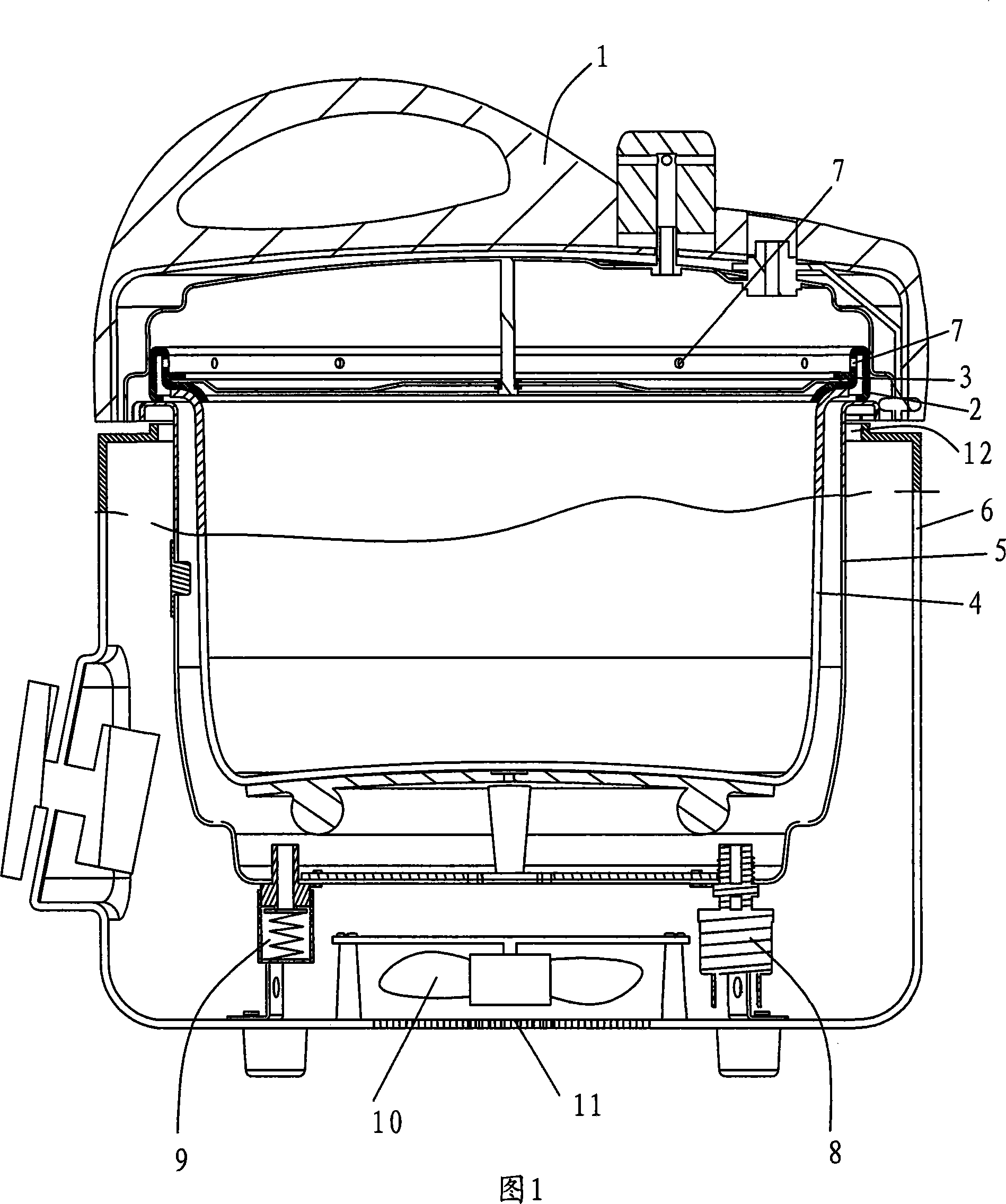
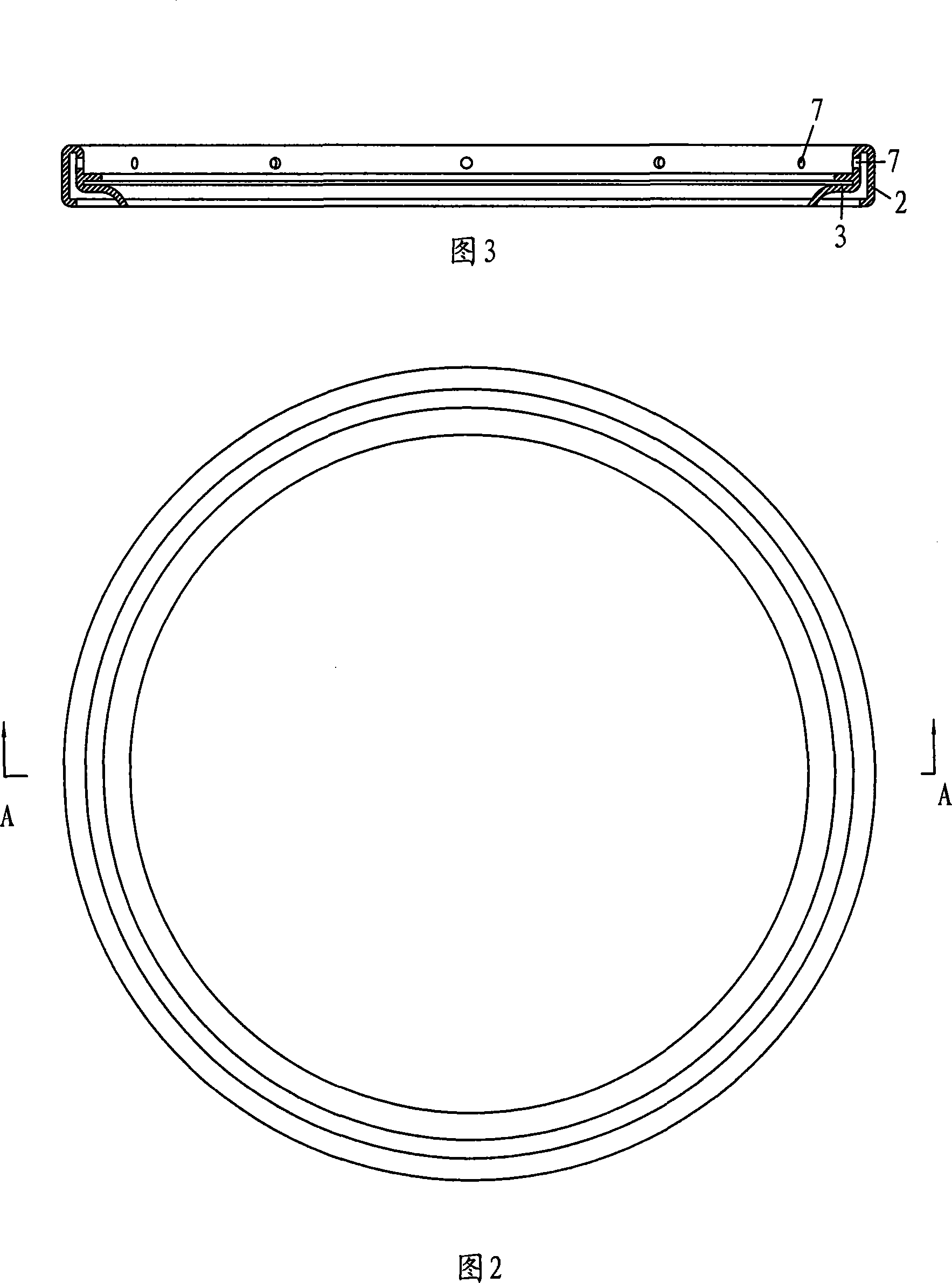
[0016] Embodiment, with reference to Fig. 1 to Fig. 3, a kind of electric pressure cooker, comprises upper cover 1, sealing ring 2, annular sealing ring 3, inner tank 4, outer tank 5, shell 6 and controller (not shown in the figure), The annular sealing ring 3 and the sealing ring 2 are a conjoined structure, the annular sealing ring 3 is located in the inner ring, the sealing ring 2 is located in the outer ring, the joint of the annular sealing ring 3 and the sealing ring 2 is provided with a steam hole 7, the sealing ring 2 and the annular The sealing ring 3 is installed on the upper cover 1 . After the upper cover 1 and the shell 6 are fastened together, the sealing ring 2 seals the upper cover 1 and the outer container 5 , and the annular sealing ring 3 and the inner container 4 seal fit. The steam of the inner bag 4 enters the outer bag 5 through the steam hole 7, so that the inner and outer walls of the inner bag bear the same pressure.

[0017] A pressure sensor 8 is a...


PUM


Abstract

The invention relates to a pressure cooker, in particular to an electrical pressure cooker, which comprises an upper cover, a sealing ring, an internal bladder, an external bladder, a shell and a controller. The sealing ring is mounted on the upper cover; the sealing ring seals the upper cover and the external bladder after the upper cover covered the shell; a steam communicating device is arranged between the two bladders. The invention has rational structure design with the internal bladder be made of aluminium, iron, ceramic and red porcelain material for it is free from being limited by pressure and the external bladder made of thick steel plate, which largely enhances the pressure beared and realizes the real high temperature and pressure. It is proved by experiment that the invention can fulfill the requirement of the traditional pressure cooker of 80KP to 100 KP. Besides, a pressure sensor of the invention is quick for sensing the pressure and rapid and precious for transferring signals together that the installation of the pressure sensor has no requirement, thus rapidly improving the production efficiency of the overall machine and also the safety and prolonging the service life. The external bladder can deduce the temperature and pressure quickly and the upper cover can be opened safely in short time.

Description

technical field [0001] The invention relates to a pressure cooker, in particular to an electric pressure cooker. Background technique [0002] The sealing ring of the existing electric pressure cooker is to seal the inner container and the upper cover, so it is the inner container that bears the pressure. Because the inner container cannot be made of iron, the strength is low and the pressure is limited, generally lower than 50KP. The working principle of the existing electric pressure cooker is that the inner container expands and deforms under pressure, presses down on the spring, and the spring is pressed until the outer container is deformed, thereby triggering the pressure control switch. This structure determines that the installation positions of the outer container and the pressure switch must be accurate. Otherwise, the pressure switch will not be able to work, so each product needs to be debugged on the whole machine, and the production efficiency is low. Moreover,...

Claims


Application Information

Patent Timeline
IPC IPC(8): A47J27/08A47J27/026
Inventor 王习之
Owner 王习之
Features
  • Generate Ideas
  • Intellectual Property
  • Life Sciences
  • Materials
  • Tech Scout
  • Unparalleled Data Quality
  • Higher Quality Content
  • 60% Fewer Hallucinations
Learn More