Dust collecting unit of vacuum cleaner

A vacuum cleaner and dust collection technology, applied in the direction of suction filter, etc., can solve the problem of low air purification ability and achieve the effect of improving air purification ability

Active Publication Date: 2008-01-23
NANJING LG PANDA APPLIANCES
View PDF0 Cites 57 Cited by
  • Summary
  • Abstract
  • Description
  • Claims
  • Application Information

AI Technical Summary

Problems solved by technology

[0017] But, the vacuum cleaner of prior art, because the foreign matter in the air only filters

Method used


Image

  • Dust collecting unit of vacuum cleaner
  • Dust collecting unit of vacuum cleaner
  • Dust collecting unit of vacuum cleaner

Examples


Embodiment Construction

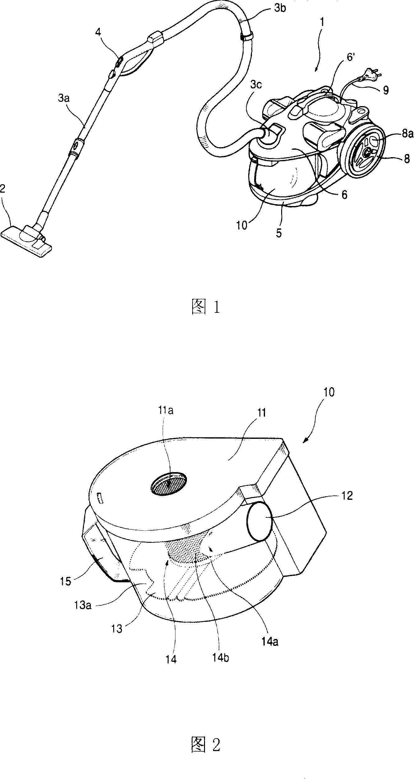
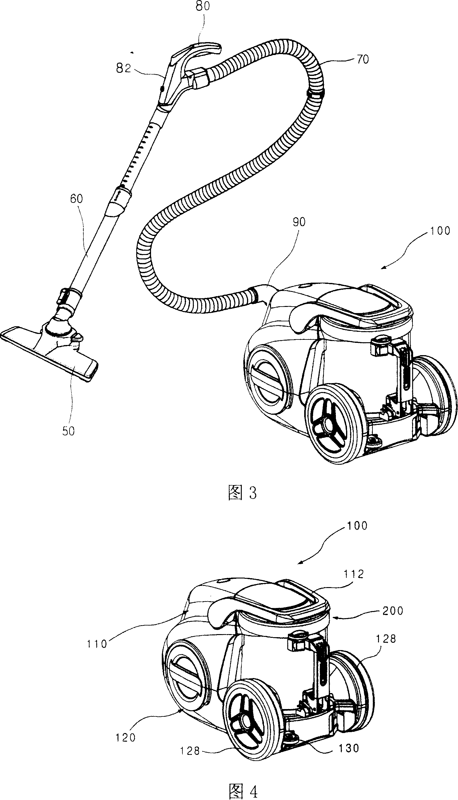
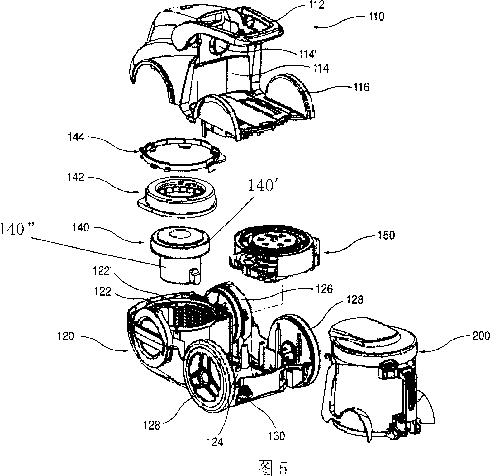
[0052] Hereinafter, the embodiments of the present invention will be described in detail with reference to the accompanying drawings.

[0053] The present invention provides a dust collecting unit of a vacuum cleaner, the structure of which includes: a first cyclone device 240 that filters foreign objects in the air for the first time; The second cyclone device 250, the second cyclone device 250 includes: a plurality of small cyclone parts 252 having different diameters to guide the air to flow in a spiral; Tube 254.

[0054] The diameters of the plurality of small cyclones 252 gradually increase from one side to the other.

[0055] A guide hole 254' is formed on the upper side of the plurality of guide pipes 254 to allow the air flowing above the guide pipe 254 to pass through, and a foreign object blocker for removing foreign objects in the air is also formed on the guide hole 254'. Rod 254".

[0056] The foreign body blocking rod 254" has a shape of one of "+" or "-".

...


PUM


Abstract

The invention discloses a dust collecting unit for a vacuum cleaner, which comprises a first cyclone device for filtering foreign bodies in air for the first time, a second cyclone device for filtering the foreign bodies in air passing the first cyclone device 240 for the second time. The invention is characterized in that: the second cyclone device comprises a plurality of small cyclone sections of different diameters guiding air to flow in helix and a plurality of guiding tubes positioned in the small cyclone sections and used for guiding air flow upward. The invention has the advantages that: with the availability of double filtering foreign bodies in air sucked outside through the flow of cyclone, enhances the air purify capacity of the vacuum cleaner, namely the advantage of filtering foreign bodies; besides, with the plurality of small cyclone sections of the different diameters, the invention can effectively utilizing the internal space of the dust collecting unit; together with the small cyclone section with larger diameter relatively, the invention enables the air flow smoothly.

Description

technical field [0001] The present invention relates to a vacuum cleaner, in particular to a dust collecting unit of the vacuum cleaner which double filters foreign objects in the air and is provided with several small cyclones of different sizes for separating foreign objects in the air. Background technique [0002] FIG. 1 is a perspective view of a prior art vacuum cleaner. As shown in the figure, the vacuum cleaner includes: a body 1 with a suction device for absorbing indoor air inside; [0003] The fuselage 1 includes: a lower fuselage 5 on which a suction device is installed; an upper fuselage 6 for preventing the components inside the lower fuselage 5 from being exposed to the outside, and an upper fuselage 6 for controlling the electronic control part (not shown) of the vacuum cleaner. [0004] A moving handle 6 ′ is circularly protruded upward on the upper surface of the upper body 6 . When the cleaner is moving, the moving handle 6' is convenient for the user to...

Claims


Application Information

Patent Timeline
IPC IPC(8): A47L9/10A47L9/16
Inventor 朴大焕徐宗玄黄弼载梁炳善金圣根
Owner NANJING LG PANDA APPLIANCES
Why Eureka
Try Eureka