Lens module

A lens module and lens barrel technology is applied in the field of lens modules that can prevent stray light from interfering with imaging, and can solve problems such as affecting the image sensing quality of an image sensor 131 and reducing the imaging quality of the lens module, so as to prevent interference. , the effect of improving the shooting quality

Inactive Publication Date: 2008-01-23
HONG FU JIN PRECISION IND (SHENZHEN) CO LTD +1
View PDF0 Cites 14 Cited by
  • Summary
  • Abstract
  • Description
  • Claims
  • Application Information

AI Technical Summary

Problems solved by technology

The above-mentioned stray light A, B and C can all interfere with the image sensor 131, affect the image sensing quality of the image sensor 131, and reduce the imaging quality of the lens module.

Method used


Image

  • Lens module
  • Lens module

Examples


Embodiment Construction

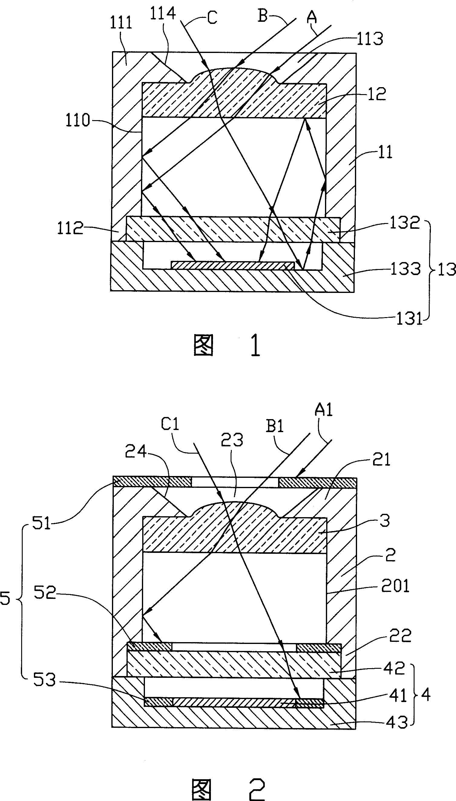
[0013] Please refer to FIG. 2 , a preferred embodiment of the lens module of the present invention includes a lens barrel 2 , a lens 3 , an image sensing module 4 and a light shielding portion 5 . The lens 3 is accommodated inside the lens barrel 2 , the image sensing module 4 is mounted on one end of the lens barrel 2 , and the light shielding portion 5 is mounted on the lens barrel 2 and the image sensing module 4 .

[0014] The lens barrel 2 is a hollow cylinder, which can be made of plastic and other materials through injection molding and other methods. The lens barrel 2 includes an inner cylindrical surface 201 , a photographing end 21 and a packaging end 22 opposite to the photographing end 21 . An opening 23 is defined in the center of the shooting end 21 , and the diameter of the opening 23 gradually decreases along the direction from the shooting end 21 to the packaging end 22 , so that a tapered side wall 24 is correspondingly formed on the lens barrel 2 at the open...


PUM


Abstract

The invention provides a lens module comprising a lens cone, a lens and a shade layer. The lens cone comprises a shooting end having an opening; the lens is accommodated in the lens cone; the shade layer is a shade film, and is mounted on the shooting end of the lens cone around the opening. The lens module can block or absorb stray light from different directions and effectively improve the picture-shooting quality.

Description

technical field [0001] The invention relates to a lens module, in particular to a lens module capable of preventing stray light from interfering with imaging. Background technique [0002] At present, most digital camera lens modules are composed of lenses, lens barrels, image sensors and other components. Its specific structure is generally that the lens is accommodated inside the lens barrel, and the image sensor is arranged on the outgoing light path of the lens. The optical image signal entering the lens barrel is focused by the lens and then reaches the image sensor, and the image sensor converts the optical image signal into an electronic image signal. [0003] Due to the limitations of the structure of the existing lens module itself, some stray light often enters the lens barrel and is received by the image sensor during actual operation, thereby adversely affecting the shooting effect. Please refer to FIG. 1 , a conventional lens module includes a lens barrel 11 ,...

Claims


Application Information

Patent Timeline
Patent Type & Authority Applications(China)
IPC IPC(8): G02B7/02
CPCG02B7/023G02B7/02
Inventor 冯琛李铭
Owner HONG FU JIN PRECISION IND (SHENZHEN) CO LTD
Why Eureka
Try Eureka