

Rotary switch device
A technology of rotary switch and switch mechanism, which is applied to electric switches, electrical components, circuits, etc., can solve the problems of increasing the number of components and increasing the axial length of the axial ignition switch, and achieves the realization of the number of components, the ease of assembly, and the increase in the number of components. the effect of strength
Inactive Publication Date: 2010-11-24
HONDA LOCK MFG CO LTD
View PDF2 Cites 0 Cited by
- Summary
- Abstract
- Description
- Claims
- Application Information
AI Technical Summary
Problems solved by technology
However, in the ignition switch disclosed in the above-mentioned Patent Document 2, the axial length of the ignition switch in the axial direction is increased, and the number of parts is increased.
Method used
View moreImage
Smart ImageViewing Examples

Examples
Embodiment 1
Embodiment 2
Embodiment 3
Login to View More PUM
 Abstract
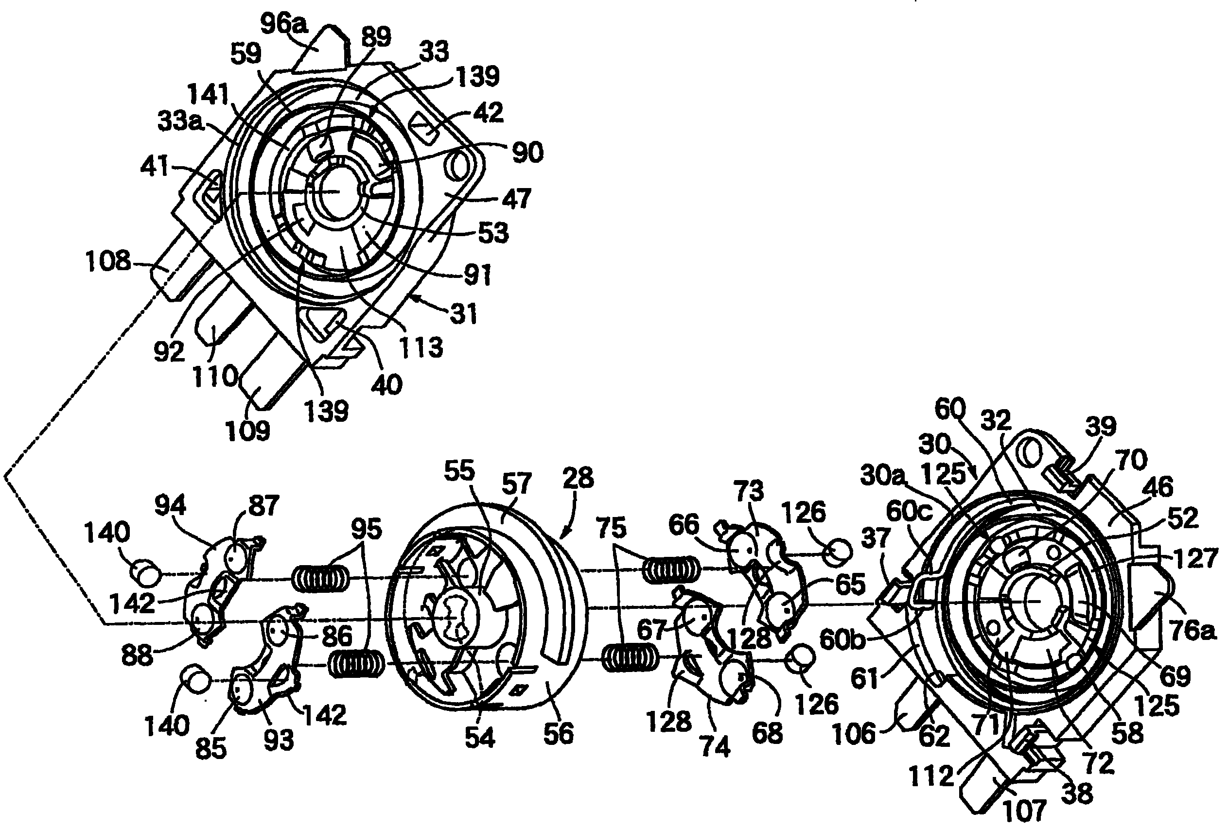
To provide a rotary switch device comprising a first switch mechanism and a second switch mechanism constituted by movable contacts rotating according to the rotation of a rotary axis and fixed contacts contacting the fixed contacts at the preset rotation position of the rotary axis respectively, capable of reducing its size and the number of parts. The first switch mechanism is constituted by movable contacts 65 to 68 arranged on one face of a single rotor 28 jointed to the rotary axis 25, in a manner of being incapable of rotating relatively, and fixed contacts 69 to 72 arranged at an innerface corresponding to one face of the rotor 28 at one half body 30 of a pair of case half bodies 30, 31 jointed to each other with the rotor 28 pinched in between, to constitute a switch case housingthe rotor 28. The second switch mechanism is constituted by movable contacts 85 to 88 arranged on the other face of the rotor 28, and fixed contacts 89 to 92 arranged at the inner face of the other case half body 31 facing the other face of the rotor 28.
Description
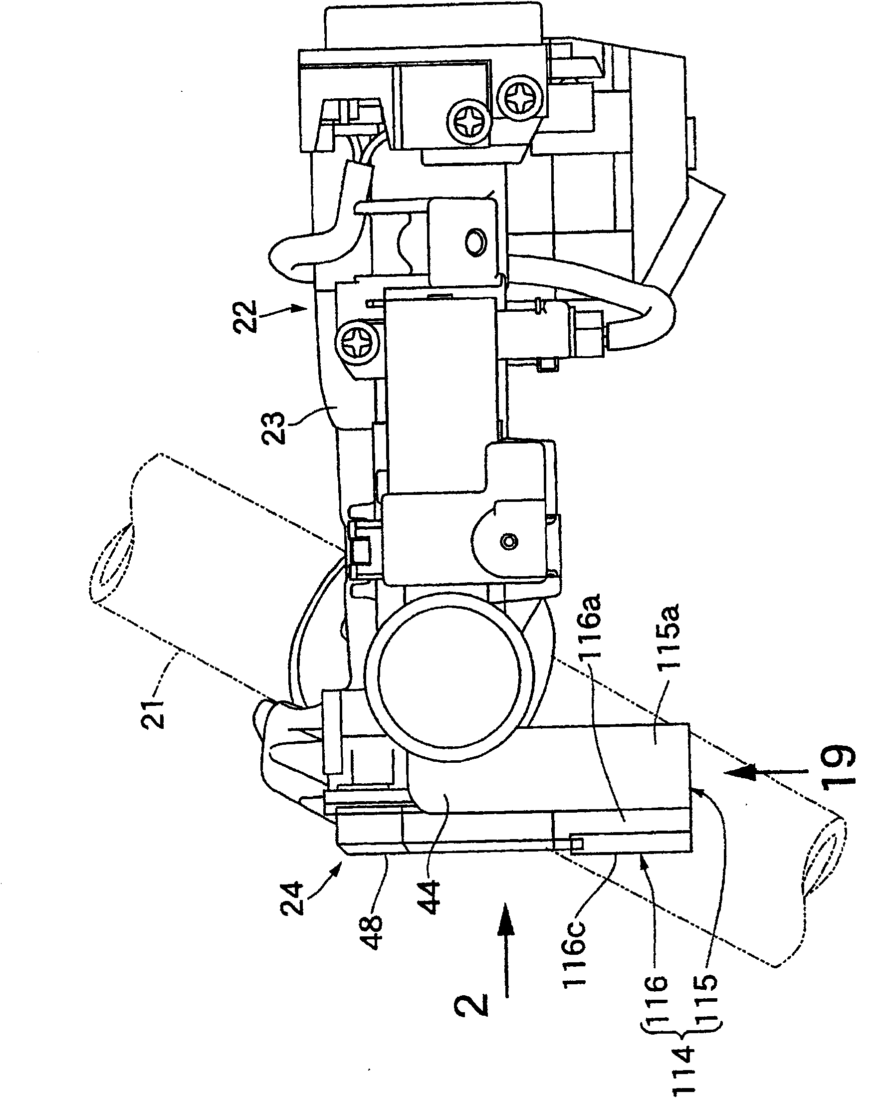
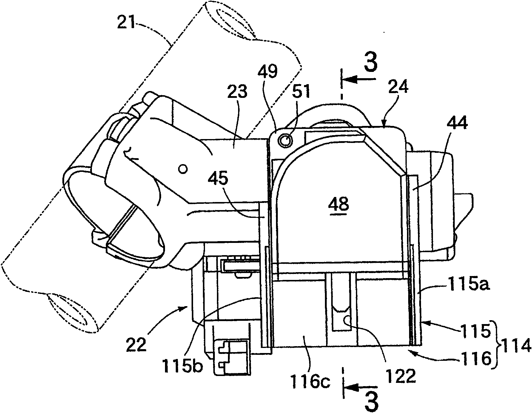
rotary switch device technical field The present invention relates to a rotary switch device having first and second switch mechanisms, the first and second switch mechanisms are respectively composed of a movable contact that rotates with the rotation of a rotary shaft and a set rotational position on the rotary shaft. The invention relates to a fixed contact that is in contact with the above-mentioned movable contact, and particularly relates to a rotary switch device suitable for use in an ignition switch for a vehicle. Background technique The ignition switch for a vehicle is required to be miniaturized because it is arranged in a limited space. However, in a general ignition switch, as disclosed in Patent Document 1, two surfaces of different diameters are formed on one surface of a rotor that rotates together with the rotating shaft. Since movable contacts are arranged in a virtual circle, and these movable contacts are brought into sliding contact with fixed contact...
Claims
Login to View More Application Information
Patent Timeline
 Patent Type & AuthorityPatents(China)
IPC IPC(8): H01H19/02H01H19/08H01H19/10H01H27/06
Inventor长沼安则原田昌彦
OwnerHONDA LOCK MFG CO LTD