
Computer flat knitting machine yarn nozzle sliding seat

A computerized flat knitting machine and sliding seat technology, which is applied in textiles and papermaking, weft knitting, knitting, etc., can solve the problems of short service life, dripping, movement obstruction, etc., to improve weaving quality, reduce wear, and reduce friction Reduced effect

Inactive Publication Date: 2008-02-06
林良金
View PDF0 Cites 2 Cited by
  • Summary
  • Abstract
  • Description
  • Claims
  • Application Information

AI Technical Summary

Problems solved by technology

Since the computerized flat knitting machine weaves yarn and velvet items, these yarns and velvet items are prone to produce yarn wool or fluff dust during the high-speed operation of the computerized flat knitting machine, and these dusts will stick to the guide rails of the computerized flat knitting machine. As a result, the movement of the above-mentioned sliding seat on the guide rail of the computerized flat knitting machine is blocked, and the knitting quality of the computerized flat knitting machine is easily affected; and this kind of sliding seat is generally made of plastic, and it moves on this kind of dusty guide rail. , is very easy to wear, so its service life is very short; if you add lubricating oil directly on the guide rail, due to the special structure of the guide rail, the lubricating oil cannot be stored on the guide rail and will directly drip
For the computerized flat knitting machine yarn feeder sliding seat with this structure, the sliding block is installed in the middle of the lower part of the main body. Under the action of the spring at the lower part, it is equivalent to a single point force acting on the guide rail. During its high-speed movement, It is easy to produce swing phenomenon, which will also cause the quality of computerized flat knitting knitting
So far, there has not been found a sliding seat that can lubricate the guide rail, move freely, keep the guide rail clean, and move on the guide rail without swinging

Method used


Image

  • Computer flat knitting machine yarn nozzle sliding seat
  • Computer flat knitting machine yarn nozzle sliding seat
  • Computer flat knitting machine yarn nozzle sliding seat

Examples


Embodiment Construction

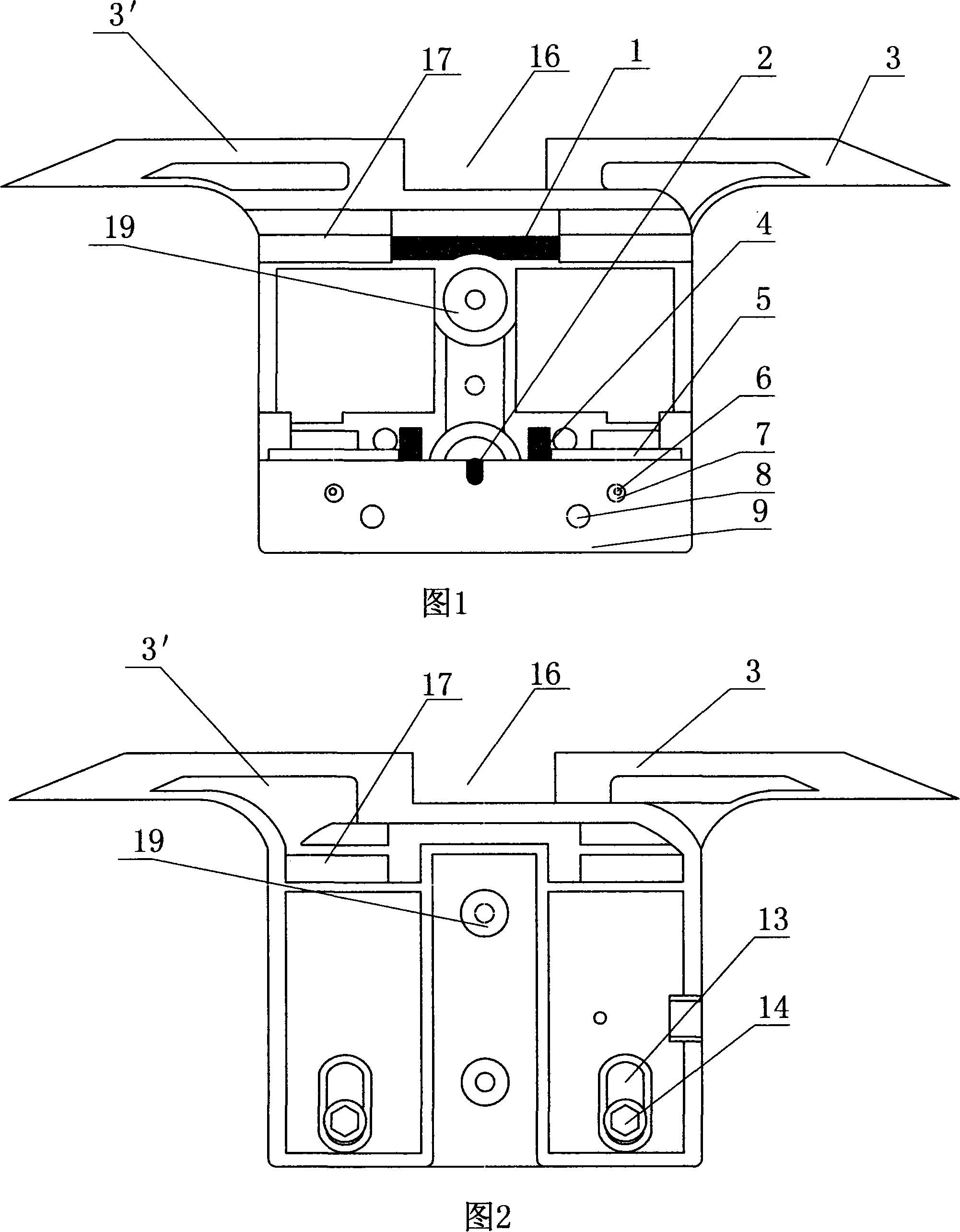
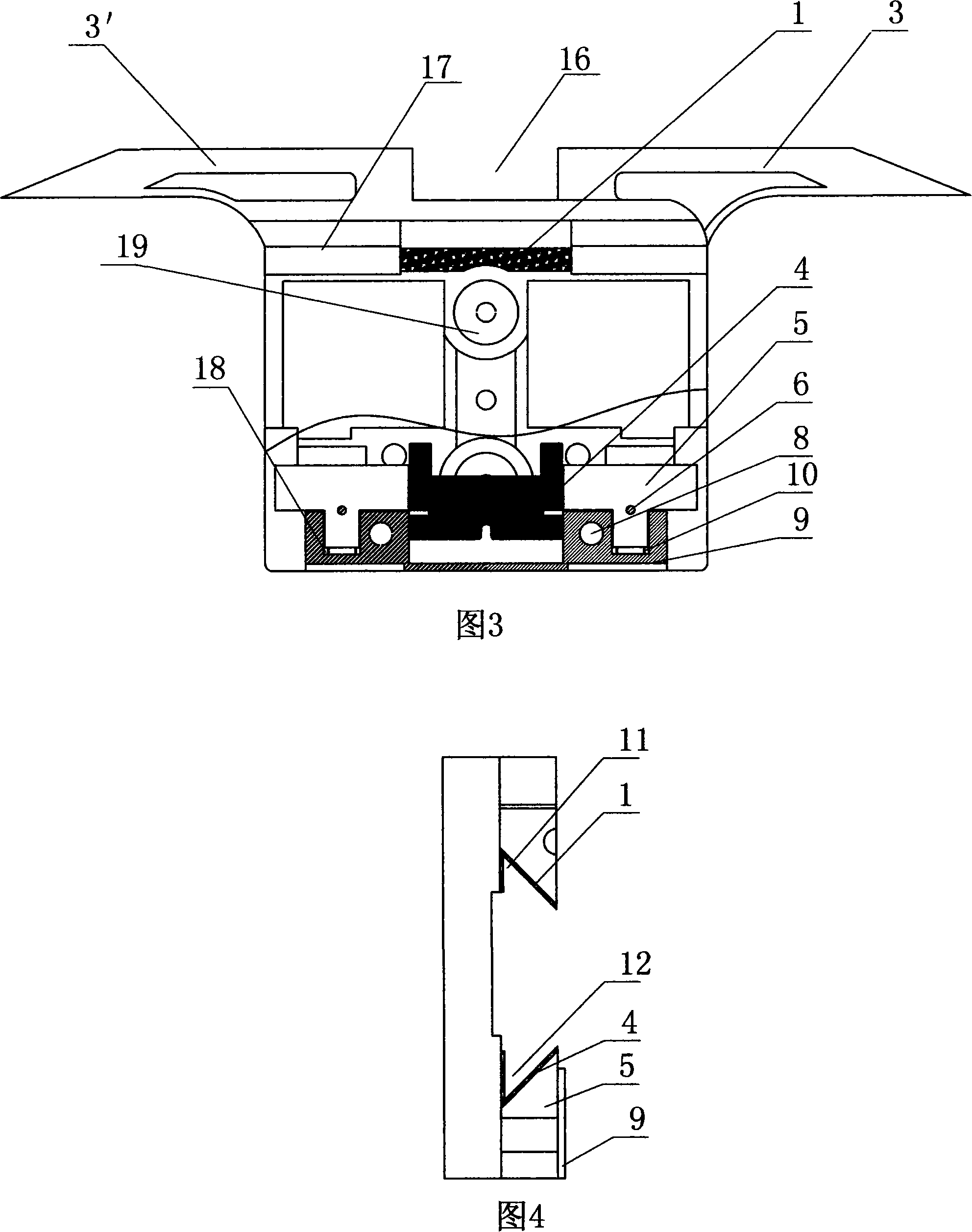
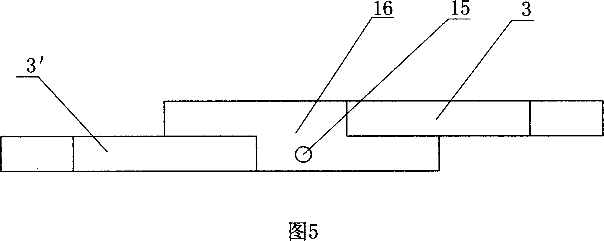
[0012] Referring to the accompanying drawings, the computerized flat knitting machine yarn feeder sliding seat has a main body 17 and a cover plate 9, the cover plate 9 is arranged on the lower part of the main body 17, and left and right slideways 3, 3' are arranged on the upper end of the main body 17, and the left and right sliding There is a certain distance between the roads 3 and 3', and a groove 16 is formed. A first angular groove 11 is arranged on the top of the body 17, and a groove 18 is arranged on the cover plate 9. The protruding part of the sliding block 5 and the spring 10 are placed together in the groove 18 after being connected. The upper end of the sliding block 5 is a wing-shaped plate with a slope on the upper side of the wing plate. The slope and the body 17 form a second angle groove 12, and the second angle groove 12 corresponds to the first corner groove 11, the so-called corresponding means that the direction of the corner is opposite, the first corne...


PUM


Abstract

The present invention discloses a yarn carrier sliding seat for computerized flat knitting machine and belongs to a fitting for driving the yarn carrier to move on the guide of a computerized flat knitting machine. The sliding seat has a body (7) and a cover plate (9), wherein the upper part of the body is arranged with a first angular groove (11); the cover plate is arranged with a sliding block (5); one end of the sliding block has a bevel, which composes a second angular groove (12) with the body; the second angular groove and the first angular groove are in correspondence and fit with the guide of the computerized flat knitting machine; the cover plate is arranged with a spring, which connects with the slider. The present invention is characterized essentially in that the middle of the upper part of the body is arranged with a first sponge-texture body (1), which is arranged in the first angular groove; a second sponge-texture body(2) is arranged between the body and the cover plate, and the second sponge-texture body is slightly higher than the angular line of the second angular groove. The present invention solves the lubrication problem and can wipe dusts on the guide so that the yarn carrier sliding seat can normally move on the guide.

Description

technical field [0001] The invention belongs to an accessory on a computerized flat knitting machine, and specifically relates to a component that moves on a guide rail of a computerized flat knitting machine to drive the yarn feeder to move. Background technique [0002] On the guide rails of the computerized flat knitting machines used for weaving, it is necessary to install a sliding seat that drives the yarn feeder to move. At present, the structure of this sliding seat also has a body and a cover plate. A first angle groove is arranged on the upper part of the body, and a sliding block is arranged on the lower part of the body. One end of the sliding block has a slope, and the slope and the body form a The second corner groove, and the second corner groove corresponds to the first corner groove, the first corner groove and the second corner groove match the guide rail of the computerized flat knitting machine, the cover plate covers the sliding block on the body, and th...

Claims


Application Information

Patent Timeline
IPC IPC(8): D04B15/00
Inventor 林良金
Owner 林良金
Learn More