Configuring matrix device of primitive colours LED

A technology for configuring matrix and three primary colors, applied in optics, instruments, electrical components, etc., can solve the problems of horizontal stripe color shift, severe, LED panel peripheral color shift, etc., and achieve the effect of reducing the color shift in the surrounding area.

Inactive Publication Date: 2008-02-06
EVERLIGHT ELECTRONICS
View PDF0 Cites 6 Cited by
  • Summary
  • Abstract
  • Description
  • Claims
  • Application Information

AI Technical Summary

Problems solved by technology

If the light mixing distance is reduced, it is easy to have the problem of horizont...

Method used


Image

  • Configuring matrix device of primitive colours LED
  • Configuring matrix device of primitive colours LED
  • Configuring matrix device of primitive colours LED

Examples


Embodiment Construction

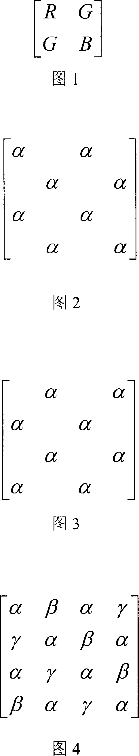
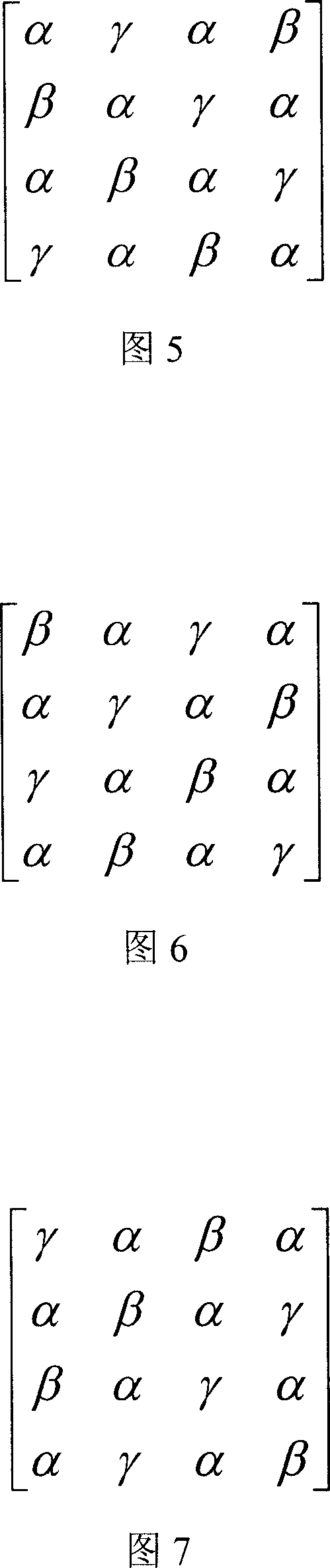
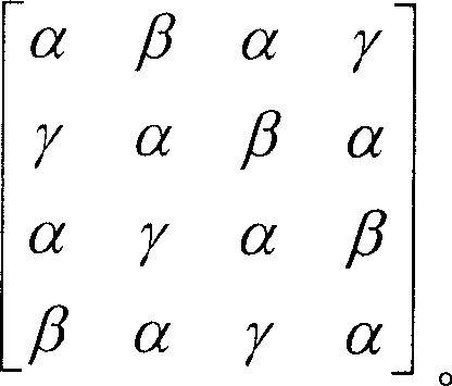
[0024] The invention provides a configuration matrix of RGB three primary color LEDs to uniformly mix white light. The RGB three primary color LED configuration matrix is ​​composed of the first LED, the second LED and the third LED, and defines a 4×4 matrix as a minimum matrix unit. Wherein, the number ratio of the first LED, the second LED and the third LED is 2:1:1. The light emitted by the above-mentioned first LED, second LED and third LED is one of the three primary colors of red, blue and green respectively. In a preferred embodiment of the present invention, the first LED is preferably a green LED, but it is not intended to limit the scope of the present invention.

[0025] There are two first LEDs in each row and each column of the minimum matrix unit, and each first LED is arranged in the minimum matrix unit at intervals up, down, left, and right. The first LED is denoted by α. Please refer to FIGS. 2-3 , which are diagrams illustrating a configuration matrix of t...


PUM


Abstract

The present invention discloses a matrix device of the configuration of the RGB LED, matrix device of the configuration of the RGB LED includes a first LED, a second LED and a third LED; wherein, the first LED, the second LED and third LED are arranged in 4 multiplied by 4, the smallest matrix unit, and the ratio of the number of the first LED, the second LED and third LED is 2 to 1to 1. The first LED, the second LED and the third LED are respectively indicated by Alpha, Beta and Gamma, in which, the repeat smallest matrix unit is arranged as shown in Figure.

Description

technical field [0001] The present invention relates to a light emitting diode (light emitting diode; LED), and in particular to a light emitting diode array used in a backlight module of a liquid crystal display. Background technique [0002] The operating principle of the backlight module is to guide the light from the backlight into a flat light source through the light guide plate to ensure the uniformity of brightness. Commonly used backlight sources for the backlight module include cold cathode fluorescent lamps and light emitting diodes, for example. Although cold cathode fluorescent lamps are currently the mainstream, the demand for light-emitting diodes is increasing day by day. Compared with cold-cathode fluorescent lamps, light-emitting diodes have the advantages of small size, long life, low driving voltage, low power consumption, and good shock resistance. [0003] Generally speaking, the LED backlight usually directly uses white LEDs or mixes red, green and b...

Claims


Application Information

Patent Timeline
IPC IPC(8): G02F1/13357H01L33/00G02F1/1335
Inventor 温宗翰刘邦言
Owner EVERLIGHT ELECTRONICS
Why Eureka
Try Eureka