Pressure generation device

A technology for generating device and pressure, applied in transportation and packaging, piston pump, liquid variable capacity machinery, etc., can solve the problem of difficulty in reducing the size of the pressure generating device, and achieve the effect of reducing the size

Inactive Publication Date: 2008-02-06
TOYOTA JIDOSHA KK
View PDF1 Cites 15 Cited by
  • Summary
  • Abstract
  • Description
  • Claims
  • Application Information

AI Technical Summary

Problems solved by technology

This also makes it difficult to reduce the size of the pressure generating device

Method used


Image

  • Pressure generation device
  • Pressure generation device
  • Pressure generation device

Examples


Embodiment Construction

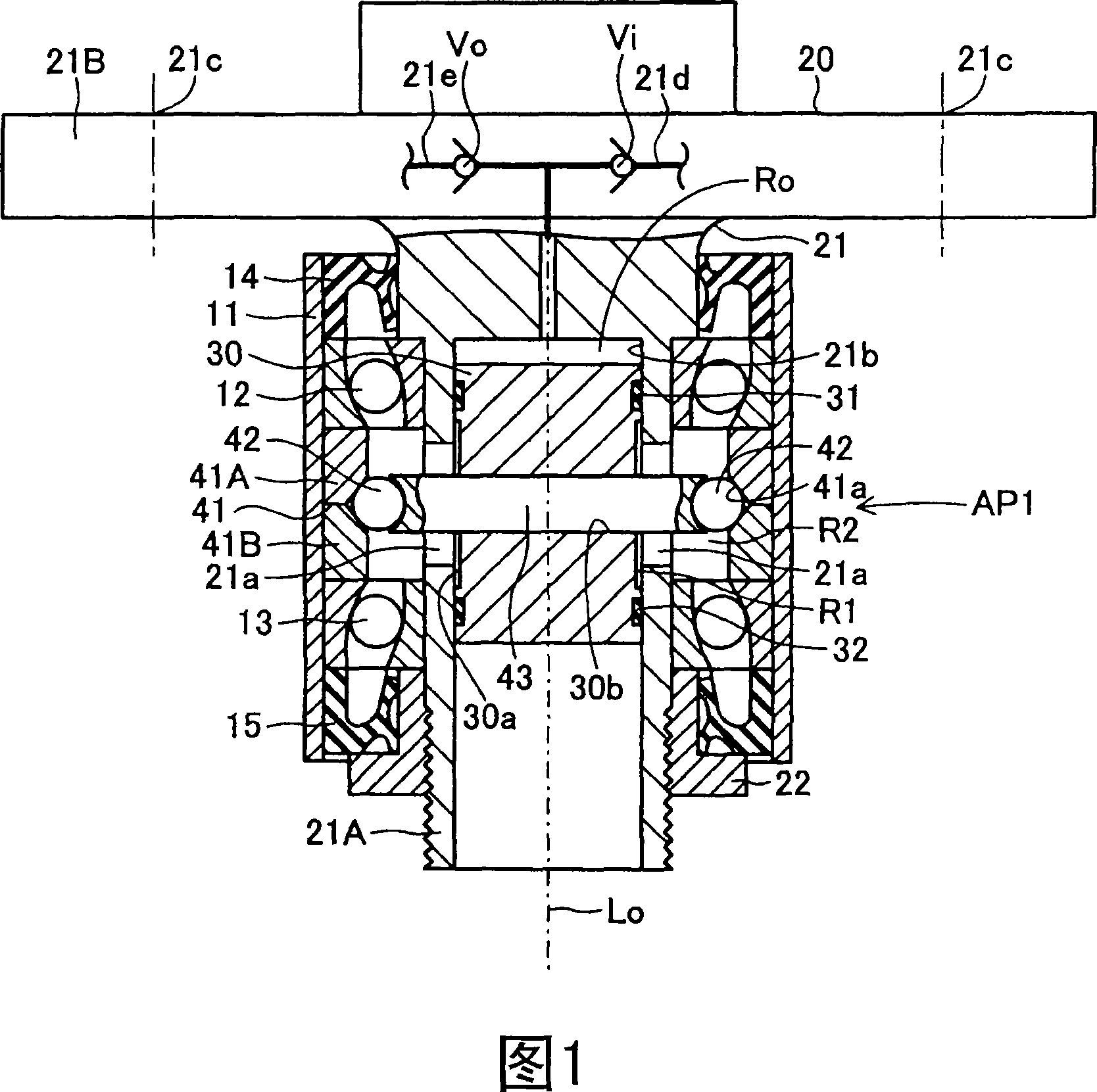
[0025] Embodiments of the present invention will be described below with reference to the drawings. Figure 1 shows a first embodiment of a pressure generating device according to the invention. The pressure generating device AP1 of the first embodiment can supply pressurized air to a tire cavity (not shown) of a wheel of a vehicle. The pressure generating device AP1 includes: a cylindrical support portion 11 serving as a supporting member and as a part of a steering knuckle; an axle hub 20 serving as a rotating member; a cylindrical piston 30 serving as a pumping member; a cam member 41 and two cam follower members. moving member 42, which cooperatively serves as a motion conversion mechanism for converting the rotational motion of the axle hub 20 relative to the cylinder support portion 11 into a reciprocating motion (vertical motion in FIG. 1 ) of the piston 30; and a rod 43, which The cam follower 42 is rotatably supported.

[0026] The cylindrical support portion 11 is f...


PUM


Abstract

A pressure-generating device includes an axle hub having a rotary shaft portion supported rotatably in a nonrotatable cylindrical support portion via bearings; a piston attached to the rotary shaft portion in a unitarily rotatable manner and so as to perform a pumping action, and, in cooperation with the rotary shaft portion, forming a pump chamber therebetween; a cam member and cam followers for converting a rotary motion of the axle hub in relation to the cylindrical support member to the pumping action of the piston; a suction path formed in the axle hub and enabling introduction of air into the pump chamber; and a discharge path formed in the axle hub and enabling discharge of air from the pump chamber.

Description

technical field [0001] The present invention relates to a pressure generating device, such as a pressure (air pressure) generating device capable of supplying pressurized air to a tire air cavity of a wheel comprising a web-type wheel held on an axle hub of a vehicle and a tire Rotatable with the axle hub, the tire is mounted on a spoked wheel whereby a tire air cavity is formed therebetween. Background technique [0002] Such a pressure generating device is disclosed in, for example, Japanese Patent Application Laid-Open (kokai) No. 11-139118. In the pressure generating device (air pressure regulator for tires) described in this publication, the pump unit is arranged on a member that rotates together with the axle for rotationally driving the axle hub of the vehicle; the pump unit is arranged along the reciprocating movement in the axial direction; one end of the piston of the pump unit abuts against the ramp of the cam member, which is non-rotatable relative to the wheel....

Claims


Application Information

Patent Timeline
Patent Type & Authority Applications(China)
IPC IPC(8): F04B35/01F04B27/08B60C23/12
CPCB60C23/137
Inventor 矶野宏
Owner TOYOTA JIDOSHA KK
Why Eureka
Try Eureka