
Blood sensor, blood testing apparatus, and method for controlling blood testing apparatus

a blood test and sensor technology, applied in the field of blood test apparatus, can solve problems such as complicated operation

Active Publication Date: 2011-11-15
PHC HLDG CORP
View PDF32 Cites 39 Cited by
  • Summary
  • Abstract
  • Description
  • Claims
  • Application Information

AI Technical Summary

Benefits of technology

[0054]The blood sensor according to the present invention is provided with the base; the detection part disposed in the base, the hollow blood collection needle provided at the front end of the base, the negative pressure generation part for applying negative pressure to the blood collection needle, and the supply path for supplying the blood collected by the blood collection needle to the detection part. Since the blood sensor itself has the blood collection needle, the skin of the patient can be punctured with the blood collection needle, and simultaneously, blood can be collected with the needle.
[0055]Moreover, the collected blood is guided as it is to the detection part without intervening manual work to be tested as it is.
[0056]Accordingly, in the blood testing apparatus provided with the above-mentioned blood sensor and the method for controlling the blood testing apparatus, there is no burden of using a puncture apparatus and a measurement apparatus separately, and blood collection and testing can be easily carried out.

Problems solved by technology

This operation is very complicated.

Method used


Image

  • Blood sensor, blood testing apparatus, and method for controlling blood testing apparatus
  • Blood sensor, blood testing apparatus, and method for controlling blood testing apparatus
  • Blood sensor, blood testing apparatus, and method for controlling blood testing apparatus

Examples


embodiment 1

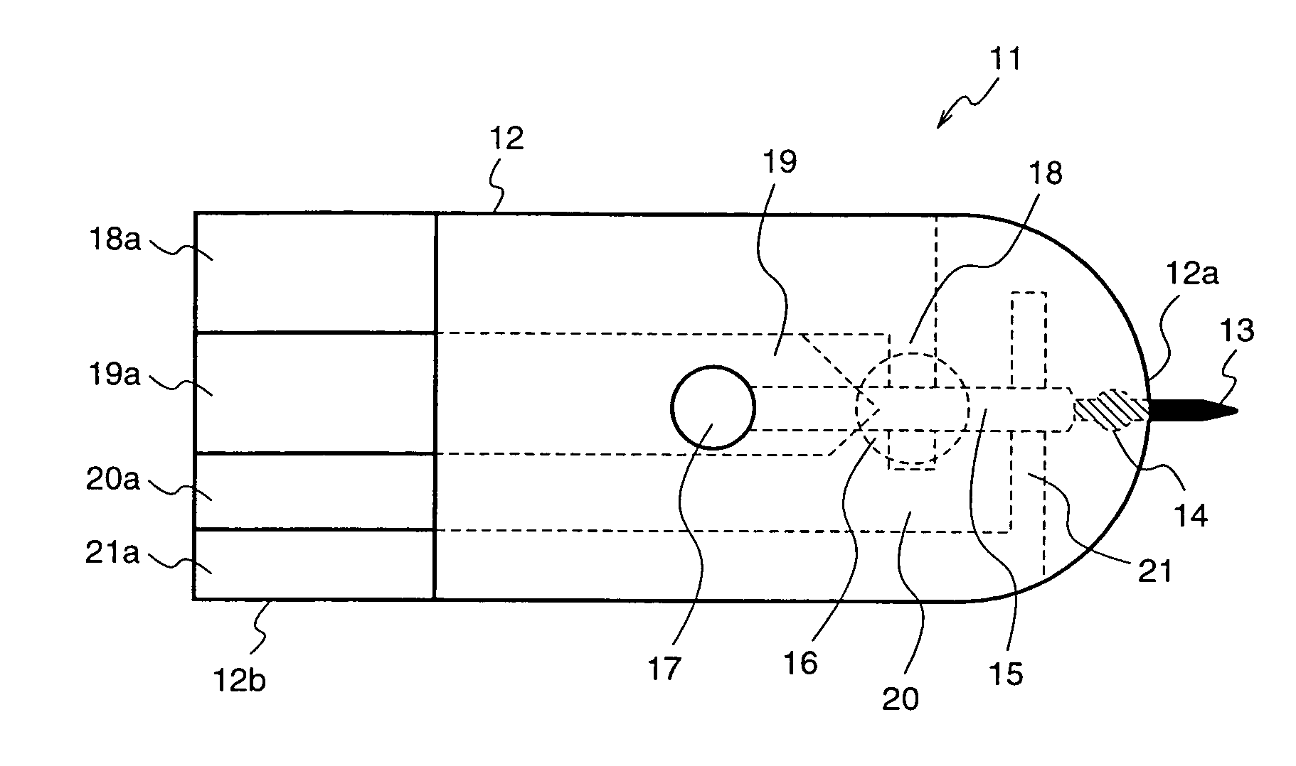
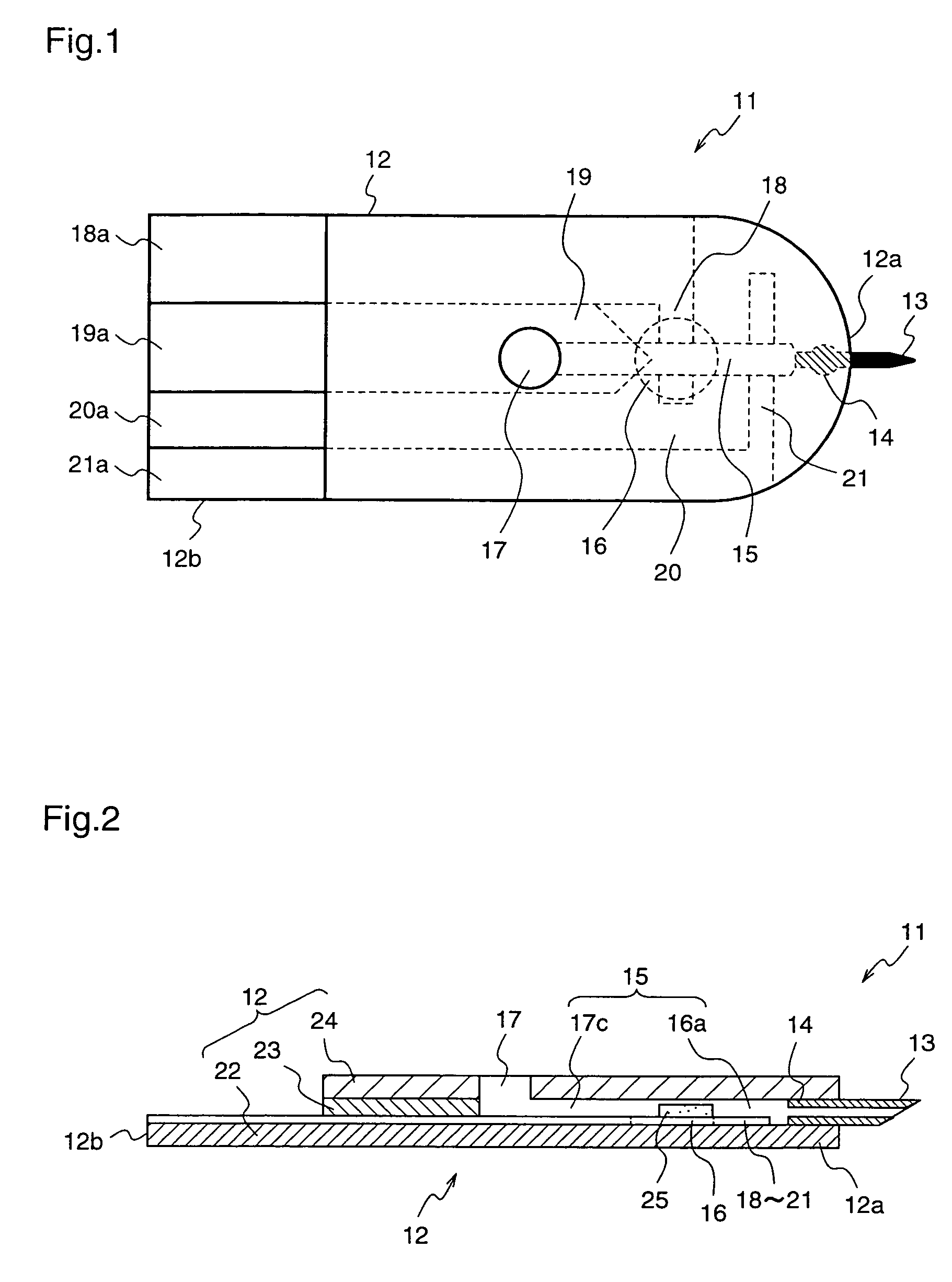
[0073]FIG. 1 is a plan view illustrating a blood sensor 11 according to a first embodiment of the present invention.

[0074]With reference to FIG. 1, a base 12 of the blood sensor 11 has a bell shape, and a hollow needle for blood collection is attached to a front end 12a of the base 12. A blood supply path 16a for supplying the blood component collected by the blood collection needle 13 to a detection part 16 is led from a attachment part 14 to which the blood collection needle 13 is attached, and this blood supply path 16a shares a portion with a negative pressure supply path 17c that forms a negative pressure generation part 17 for applying negative pressure to the follow portion of the blood collection needle 13. In order to simplify the following description, it is assumed that the negative pressure supply path 17c and the blood supply path 16a constitute a supply path 15.

[0075]The detection part 16 includes detection electrodes 18, 19, 20, and 21 comprising a conductive material...

embodiment 2

[0097]FIGS. 4(a)-4(d) are front views and side views of various shapes of blood collection needles 13 according to a second embodiment of the present invention. The same components are given the same reference numerals to simplify the description.

[0098]As a material of the blood collection needle 13 shown in FIGS. 4(a)-4(d), metal (SUS304) or plastic (PEEK: polyether ether ketone) may be used. When metal is adopted, a strong and easy-to-puncture blood collection needle 13 can be produced.

[0099]When plastic is used, the blood collection needle 13 can be easily fabricated by extrusion molding, and further, the needle 13 has elasticity that reduces needle-stick accidents to the patient.

[0100]In FIG. 4(a), a blood collection needle 13a has a triangular side surface, and its length 26a and height 27a are 1 mm and 0.155 mm, respectively. An angle 28a at the front end is 15°. A diameter 29a of the side surface is 0.2 mm, and a through-hole having a diameter 30a of 0.05 mm is formed in the ...

embodiment 3

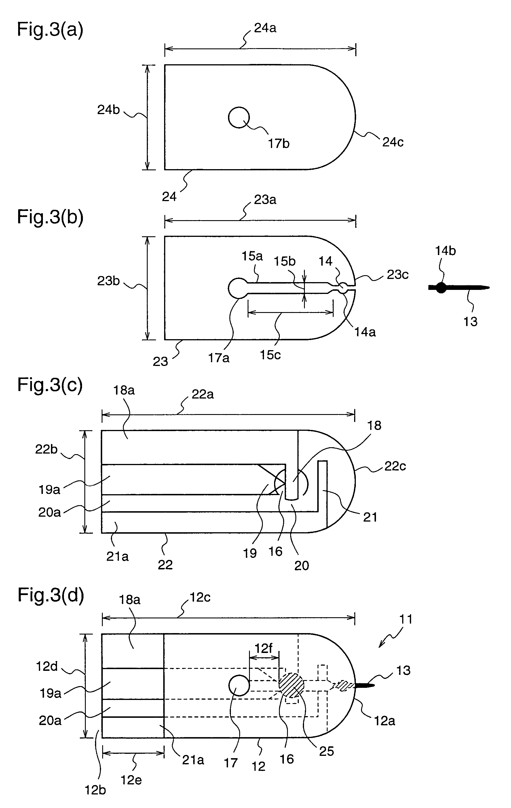
[0115]FIGS. 5(a)-5(d) are plan views of a substrate 22, a spacer 23, and a cover 24 which constitute a blood sensor 11 according to a third embodiment of the present invention, before disconnection of a blood collection needle cover. The same components are given the same reference numerals to simplify the description.

[0116]FIG. 5(a) is a plan view of a cover 24 and a blood collection needle cover 32 connected to the cover 24, before disconnection of the needle cover 32, in the blood sensor 11 according to the third embodiment. The blood collection needle cover 32 is formed of the same material as and integrally with the cover 24.

[0117]To be specific, the blood collection needle cover 32 is formed so as to cover a front end portion 24c of the cover 24, and is connected to the cover 24 at both ends 32a and 32b of the circular front end portion 24c of the cover 24.

[0118]Further, a notch 32c is formed at a position in the blood collection needle cover 32 corresponding to the blood coll...


PUM


Abstract

A blood sensor including a base (12), a detection part (16) disposed on the base (12), a blood collection needle (13) disposed at a front end (12a) of the base (12), a negative pressure generation part (17) for applying negative pressure to a portion of the blood collection needle (13), and a supply path (15) for supplying blood collected by the blood collection needle (13) to a detection part (16).

Description

FIELD OF THE INVENTION[0001]The present invention relates to a blood sensor, a blood testing apparatus, and a method for controlling the blood testing apparatus.BACKGROUND OF THE INVENTION[0002]Hereinafter, a conventional blood sensor and a blood testing apparatus using the blood sensor will be described with respect to a sensor and a testing apparatus used for diabetes testing.[0003]A diabetic patient measures his / her blood glucose level periodically, and injects insulin on the basis of the blood glucose level to keep a normal blood glucose level. Conventionally, in order to measure blood glucose level, a small amount of blood is collected from a finger tip or the like of a patient using a puncture unit, and then the blood glucose level of the collected blood is measured using a measurement unit.[0004]More specifically, as shown in FIG. 14, initially a puncture needle port 2 of a puncture unit 1 is applied to a finger tip or the like of a patient. Thereafter, a button 3 is pressed....

Claims


Application Information

Patent Timeline
Patent Type & Authority Patents(United States)
IPC IPC(8): A61B5/00
CPCA61B5/1411A61B5/1486A61B5/14535A61B5/150022A61B5/150083A61B5/150099A61B5/150229A61B5/150282A61B5/150358A61B5/150389A61B5/150511A61B5/150541A61B5/150618A61B5/150717A61B5/15113A61B5/15117A61B5/1519A61B5/157A61B5/150977
Inventor FUJIWARA, MASAKITERASHIMA, NORIYOSHIAIBARA, SHUSEI
Owner PHC HLDG CORP
Learn More