Environmental Mechanical Test Apparatus

Inactive Publication Date: 2009-12-24
SCHLUMBERGER TECH CORP
View PDF2 Cites 37 Cited by
  • Summary
  • Abstract
  • Description
  • Claims
  • Application Information

AI Technical Summary

Benefits of technology

[0009]The present invention provides significant advantages, including: (1) providing a means for testing the mechanical performance of a material after, and / or during, sustained exposure to environmental conditions of interest; (2) providing a means for testing the mechanical performance of a material while the material is exposed to a fluid of interest at a desired temperature and pressure; and (3) providing a means for visually observing an ongoing test of a material while the material is exposed to a fluid of interest at a desired temperature and pressure.

Problems solved by technology

Such harsh environments are often found in oilfield operations.

Method used


Image

  • Environmental Mechanical Test Apparatus
  • Environmental Mechanical Test Apparatus
  • Environmental Mechanical Test Apparatus

Examples


Embodiment Construction

[0019]Illustrative embodiments of the invention are described below. In the interest of clarity, not all features of an actual implementation are described in this specification. It will of course be appreciated that in the development of any such actual embodiment, numerous implementation-specific decisions must be made to achieve the developer's specific goals, such as compliance with system-related and business-related constraints, which will vary from one implementation to another. Moreover, it will be appreciated that such a development effort might be complex and time-consuming, but would nevertheless be a routine undertaking for those of ordinary skill in the art having the benefit of this disclosure.

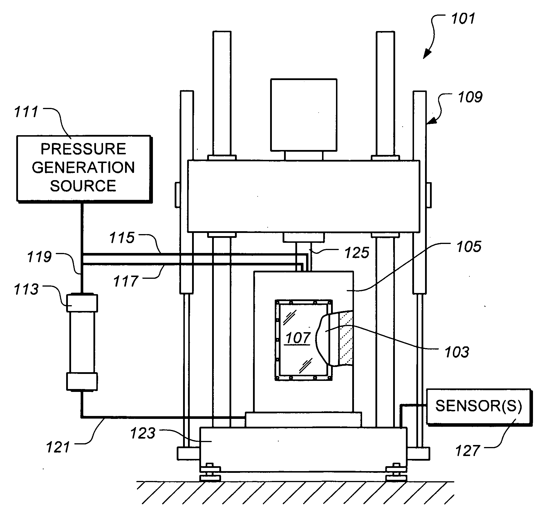
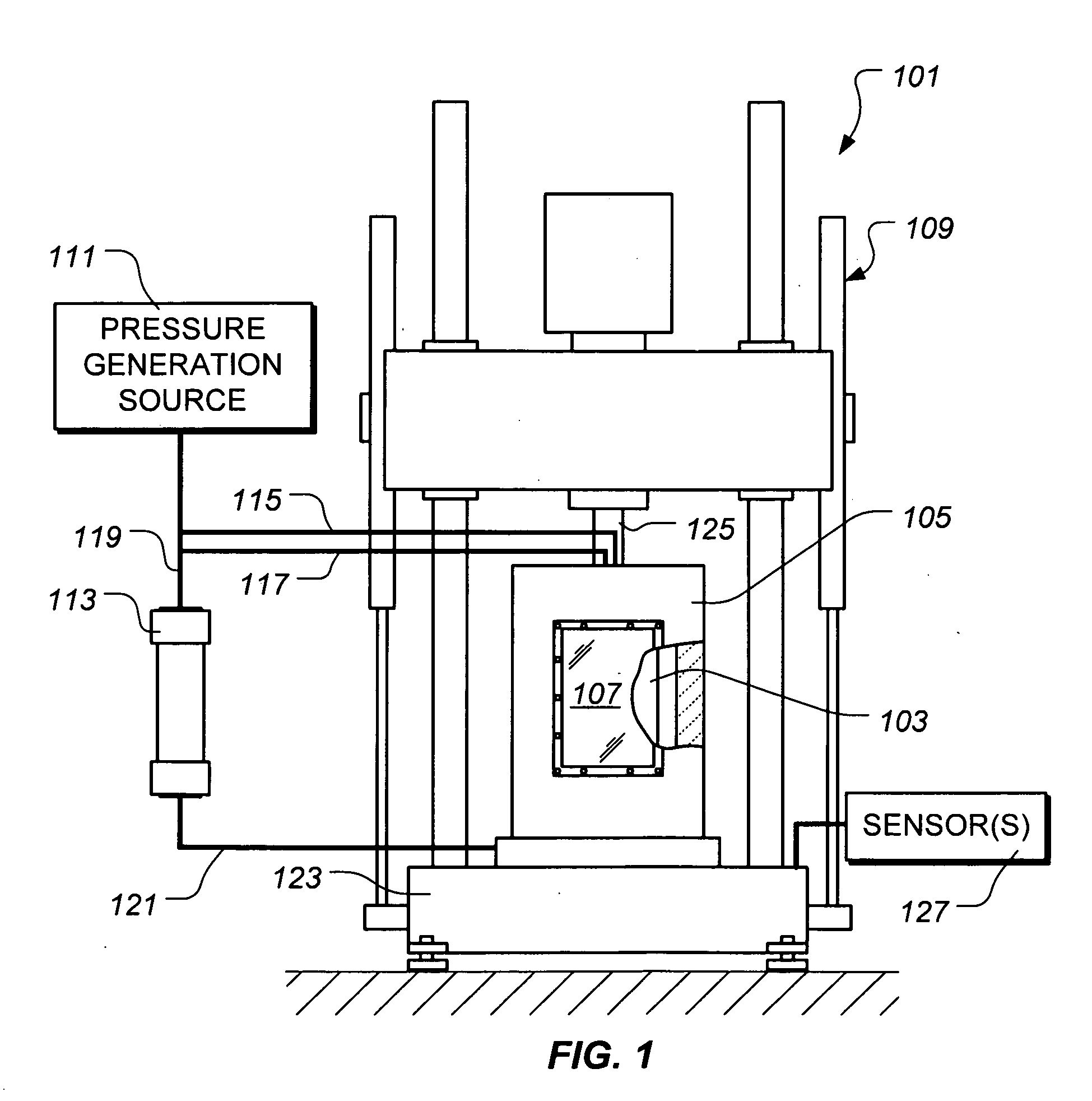
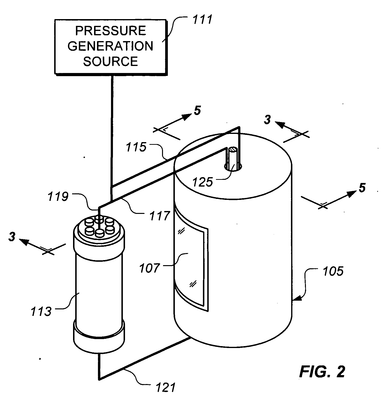
[0020]The present invention represents a visual environmental mechanical test apparatus for testing one or more mechanical properties of a material while the material is submerged in a fluid at a desired temperature and pressure. While the invention is not so limited, the test ap...


PUM

PropertyMeasurementUnit
temperaturesaaaaaaaaaa
pressuresaaaaaaaaaa
environmental mechanical test apparatusaaaaaaaaaa

Abstract

An environmental mechanical test apparatus includes a pressure generation source and an isolation cylinder in fluid communication with the pressure generation source. The test apparatus further includes a pressure containment cell configured to receive a test specimen, an environmental chamber disposed about the pressure containment cell, and a load frame operably associated with the pressure containment cell. The pressure containment cell is in fluid communication with the pressure generation source and the isolation cylinder and includes a viewing window.

Description

BACKGROUND OF THE INVENTION[0001]1. Field of the Invention[0002]The present invention relates to an apparatus for mechanically testing materials in environments of interest, such as harsh environments.[0003]2. Description of Related Art[0004]The development and qualification of materials for service in harsh environments requires testing the mechanical performance of such materials after, and / or during, sustained exposure to the harsh environment. Harsh environments include environments that exhibit extreme pressures and / or temperatures and / or wet environments that include corrosive fluids. Such harsh environments are often found in oilfield operations. Conventionally, materials that are being tested for service in harsh environments are often first subjected to a harsh environment then removed from the harsh environment for mechanical testing. Therefore, the true performance of the material of interest is not measured while the material is being subjected to the harsh environment. ...

Claims


Application Information

Patent Timeline
Patent Type & Authority Applications(United States)
IPC IPC(8): G01N17/00
CPCG01N3/08G01N17/002G01N2203/0017G01N2203/0242G01N2203/0232G01N2203/024G01N2203/0226E21B49/08G01N33/24
Inventor YAKIMOSKI, TODDCRASTER, BERNADETTEJACOBS, SCOTTHAMMAMI, AHMED
Owner SCHLUMBERGER TECH CORP
Why Eureka
Try Eureka