Double-resonance girder type micro mechanical pressure sensor

A vibrating beam type micro-mechanical pressure technology, which is applied in the measurement of fluid pressure, measurement of fluid pressure through electromagnetic elements, piezoelectric/electrostrictive/magnetostrictive devices, etc., can solve the problem of difficult processing, high production cost, and actual temperature There are problems such as deviation, so as to reduce the difficulty of production, improve the yield and improve the precision

Inactive Publication Date: 2008-10-08
BEIHANG UNIV
View PDF0 Cites 39 Cited by
  • Summary
  • Abstract
  • Description
  • Claims
  • Application Information

AI Technical Summary

Problems solved by technology

Although the above two sensors have been marketed at present, their common problems are complex structure, high production cost, and relatively low yield. According to the current level of micromachining technology in my country, processing is very difficult.
On the other hand, for resonant sensors, regardless of electrostatic excitation, electromagnetic excitation, or other excitation methods, changes in environmental factors such as temperature will inevitably cause changes in the resonant frequency of sensitive components, resulting in measurement errors
Among them, the drift of the resonan

Method used


Image

  • Double-resonance girder type micro mechanical pressure sensor
  • Double-resonance girder type micro mechanical pressure sensor
  • Double-resonance girder type micro mechanical pressure sensor

Examples


Embodiment Construction

[0025] The present invention will be described in detail below in conjunction with a specific embodiment and accompanying drawings.

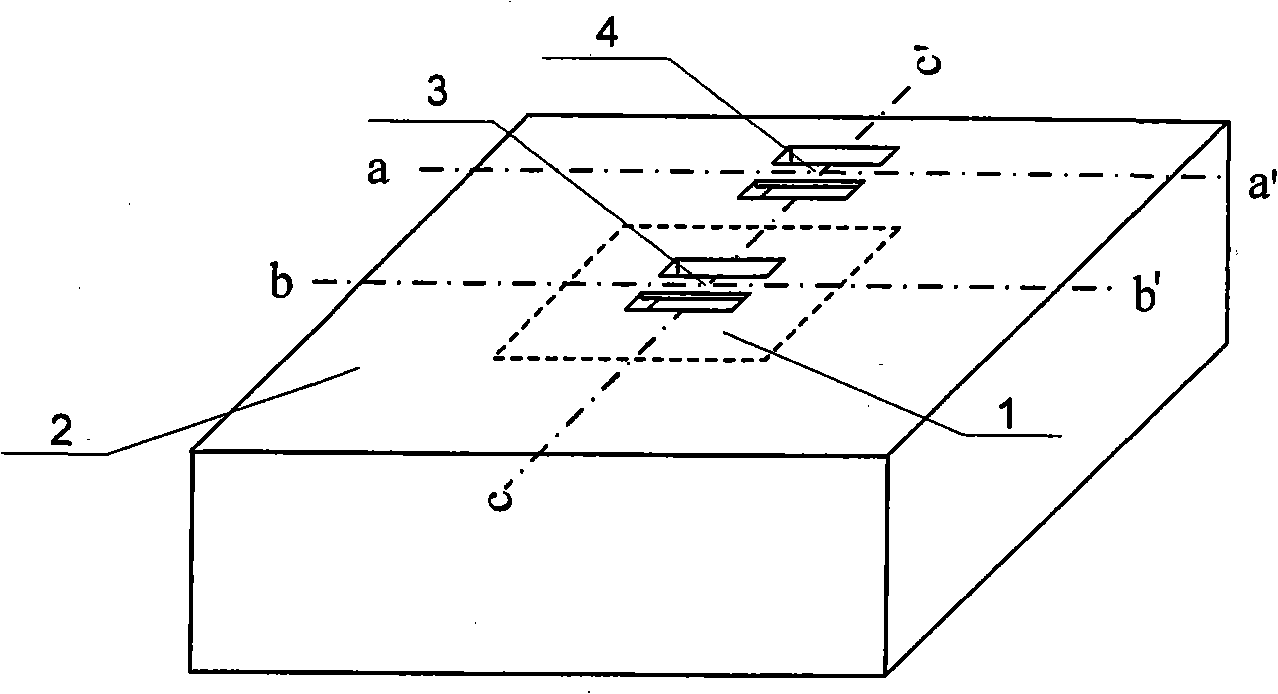
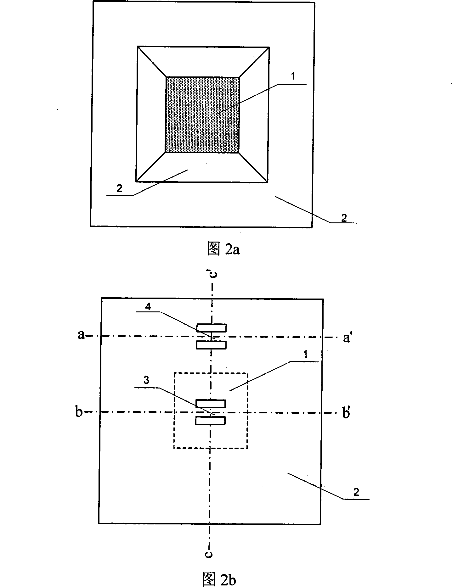
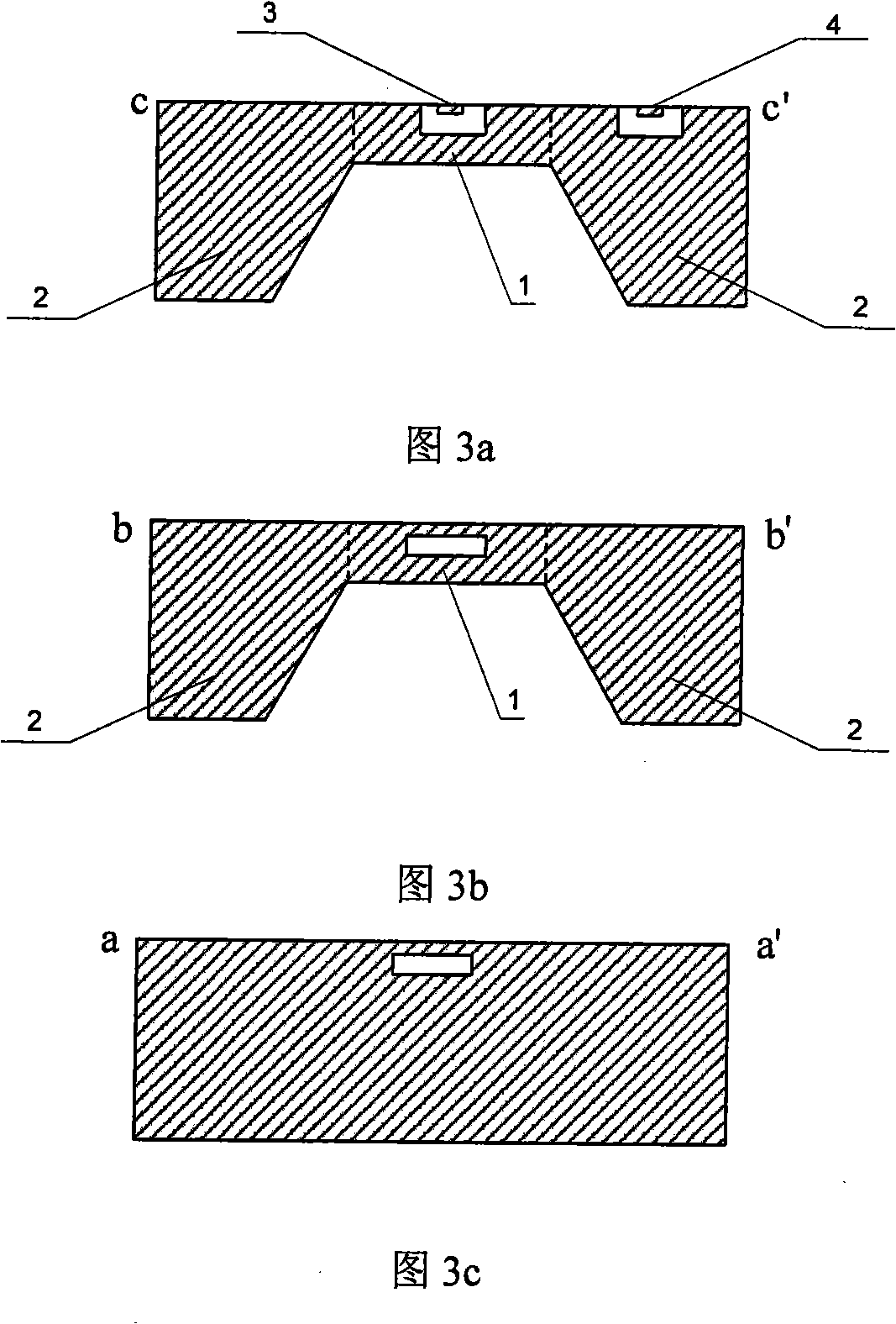
[0026] Such as figure 1 , figure 2 , image 3 As shown, a double-resonant beam micromechanical pressure sensor of this embodiment includes four parts: a pressure-sensitive diaphragm 1, a non-pressure-sensitive area 2, a resonant working beam 3 and a resonant compensation beam 4; the materials used in each part are the same Consistent, it can be silicon, or silicon nitride, or quartz, or metal tungsten, or permanent elastic alloy and other materials. The size of the square diaphragm is much larger than the thickness in the side length direction; the non-pressure-sensitive area 2 is located around the pressure-sensitive diaphragm 1 and is a structure with holes in the middle. The aperture of the diaphragm 1 is exactly the same, starting from the thickness position that is flat with the lower surface of the pressure-sensitive diaphragm 1, the a...


PUM


Abstract

A bi-resonant beam micromachine pressure sensor mainly comprises sensing membrane, non-sensing area, resonant working beam and resonant compensating beam; the centre of the structure is rectangular sensing membrane for sensing the tested pressure to generate corresponding deformation; the peripheral part of the sensing membrane is non-sensing area which does not sense the tested pressure; periphery of the sensing membrane is clamped in the inner wall of the non-sensing area; both ends of the resonant working beam are clamped at the centre of upper surface of the sensing membrane to sense the tested pressure so as to change the resonance frequency and obtain the corresponding tested pressure valve through testing the resonance frequency by the closed loop system; both ends of the resonant compensating beam are clamped in the upper surface of the non-sensing area and are parallel to the resonant working beam and have the same physical dimension with the resonant working beam; the resonant compensating beam does not sense the tested pressure and only senses the temperature the same with the resonant working beam and other environmental factors; executing difference by using the resonance frequency of the resonant working beam and the resonance frequency of the resonant compensating beam is able to remove the change of the resonance frequency of the resonant working beam caused by temperature and other environmental factors so as to improve the measuring precision and stability of the sensor.

Description

technical field [0001] The invention belongs to the technical field of micro-electro-mechanical systems, and relates to a double-resonance beam type micro-mechanical pressure sensor. Background technique [0002] The pressure sensor is a sensor widely used in aviation, aerospace and other fields to measure atmospheric pressure. Resonant micromechanical pressure sensors are very suitable for aerospace applications due to their small size, light weight, fast dynamic response, strong anti-interference ability, and high measurement accuracy, and have become a research hotspot at home and abroad. At present, many foreign scientific research institutions are conducting related research and have related products coming out. Typical products include J.C.Greenwood and D.W.Satchell, Miniature silicon resonant pressure sensor, IEE Proc.135(5), Greenwood et al. 1988: 369-372. and J.Greenwood and T.Wray, High accuracy pressure measurement with a silicon resonant sensor, Sensors and Acti...

Claims


Application Information

Patent Timeline
IPC IPC(8): G01L9/00B81B7/02
Inventor 樊尚春汤章阳刘广玉
Owner BEIHANG UNIV
Why Eureka
Try Eureka