
Rolling element accommodating belt, linear guide apparatus and metallic mold for manufacturing rolling element accommodating belt

A technology of rolling elements and metal molds, applied to bearing elements, mechanical equipment, linear motion bearings, etc., can solve the problems of increased manufacturing costs and achieve stable performance

Inactive Publication Date: 2008-02-13
NSK LTD
View PDF6 Cites 6 Cited by
  • Summary
  • Abstract
  • Description
  • Claims
  • Application Information

AI Technical Summary

Problems solved by technology

However, when the above countermeasures are taken, the manufacturing cost will increase

Method used


Image

  • Rolling element accommodating belt, linear guide apparatus and metallic mold for manufacturing rolling element accommodating belt
  • Rolling element accommodating belt, linear guide apparatus and metallic mold for manufacturing rolling element accommodating belt
  • Rolling element accommodating belt, linear guide apparatus and metallic mold for manufacturing rolling element accommodating belt

Examples


no. 1 example

[0094] First, a first embodiment of the present invention according to the first to fifth aspects of the present invention will be described.

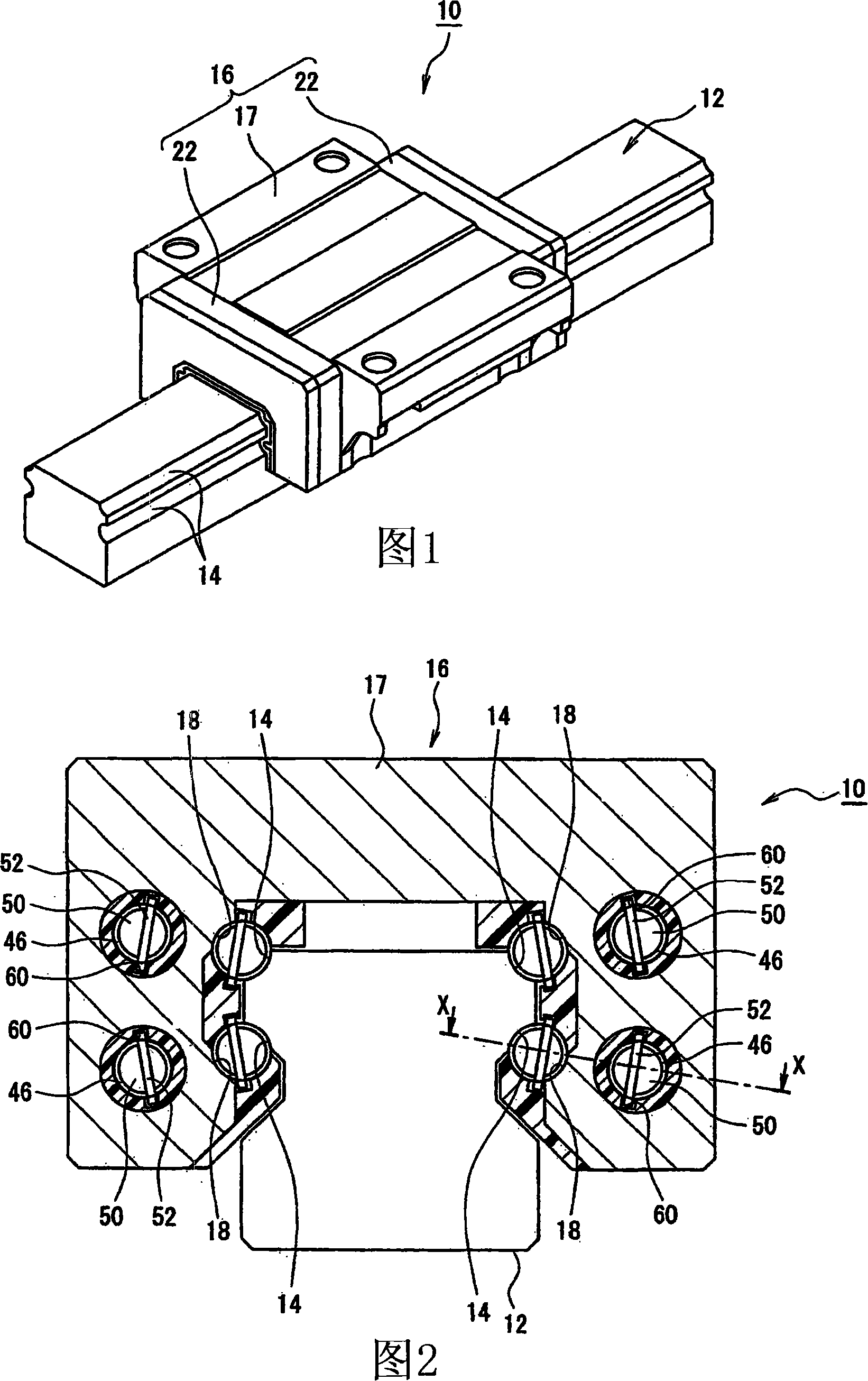
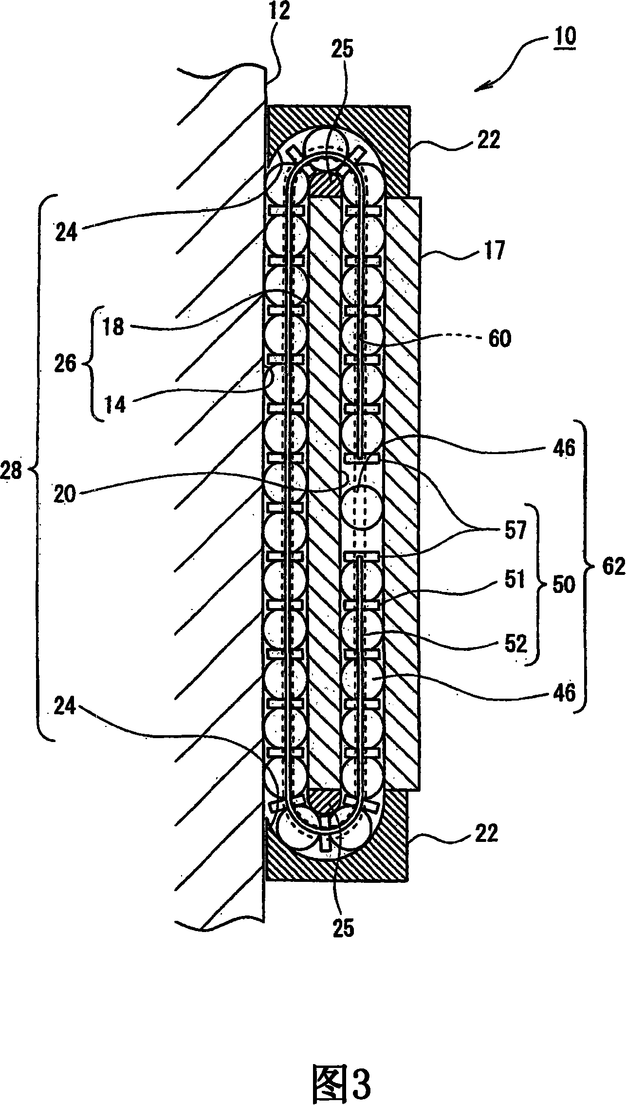
[0095] FIG. 1 is a perspective view of a linear guide showing a first embodiment of a linear guide apparatus having a rolling element accommodating belt of the present invention. Figure 2 is a front view showing the linear guide of Figure 1 with the end cap removed from the linear guide. Fig. 3 is a sectional view taken along the line X-X of the linear guide shown in Fig. 2 .

[0096] As shown in FIGS. 1 and 2, the linear guide 10 includes: a guide rail 12 having a rolling element guide surface 14; and a slider 16 mounted on the guide rail 12 so that the slider 16 can move relative to the guide rail 12. .

[0097] The guide rail 12 has a substantially square cross-section. On both sides of the guide rail 12, four rolling element guide surfaces 14 are provided, that is, two rolling element guide surfaces 14 are provided on one side o...

no. 2 example

[0142] Next, second and third embodiments according to the sixth to eleventh aspects of the present invention will be described.

[0143] The basic structures of the rolling element accommodating belt, the linear guide device, and the metal mold are the same, and detailed descriptions about similar members will be omitted.

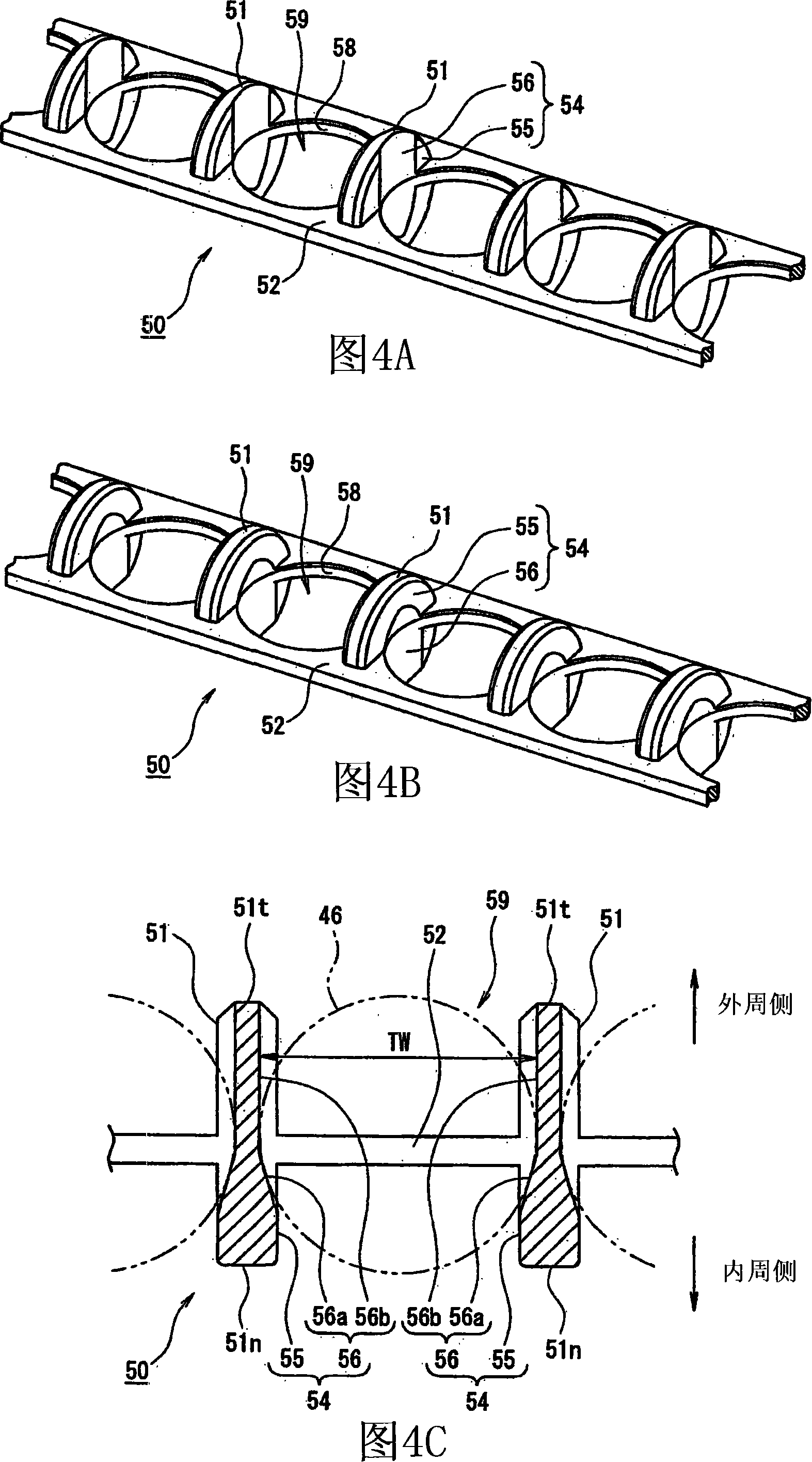
[0144] As shown in Figures 13B and 13C, the boundary position PL is set at the position of the boundary between the non-contact surface 155 and the contact surface 156 of each spacer part 151, and the product structure 193 of the upper mold 191 and the lower mold 192 is on the boundary. Demarcation at position PL. As shown in FIG. 14 , in this metal mold 190 , a pouring port 194 for pouring molten synthetic resin into a product structure portion 193 is provided in a lower mold 192 . At positions corresponding to the ends on the inner peripheral side of the spacer portion 151 to be formed, a necessary number of pouring ports 194 are provided. In the examp...


PUM


Abstract

The metallic mold (90) includes a product configuration portion (93) formed between an upper mold (91) and a lower mold (92). This product configuration portion (93) is composed so that a rolling element accomodating belt (50) formed by this product configuration portion (93) can include spacer portions (51) interposed between balls (46) adjacent to each other in an infinite circulating passage and also include connecting arm portions (52) for connecting the spacer portions to each other and so that the balls (46) can be aligned in the alignment direction in the infinite circulating passage. The upper mold (91) has a splitting structure. A rolling element accomodating belt for linear guide apparatus, linear guide apparatus and a metallic mold for manufacturing of the rolling element accomodating belt are subjects of the invention.

Description

technical field [0001] The present invention relates to a rolling element accommodating belt, a linear guide device and a metal mold for manufacturing the rolling element accommodating belt. Background technique [0002] In linear guides, a slider is moved relative to a guide rail by a plurality of rolling elements that roll and run in an endless running channel. However, in the linear guide device, although the slider moves relative to the guide rail, the rolling elements roll and move in the same direction. Therefore, the rolling elements adjoining each other rub against each other. Therefore, the rolling elements cannot roll smoothly. Thus, the noise intensity is improved and the rolling elements are easy to wear. In order to solve the above problems by suppressing the generation of noise and allowing the linear guide to operate smoothly, a rolling element accommodation belt in which the rolling elements are aligned in an aligned direction in an infinitely running path...

Claims


Application Information

Patent Timeline
Patent Type & Authority Applications(China)
IPC IPC(8): B29C45/26B29C45/33F16C33/38F16C29/06
Inventor 松本淳
Owner NSK LTD
Learn More