Dual-side scanning device

A technology for double-sided scanning and scanning of documents, applied in image communication, electrical components, etc., can solve the problem of high cost

Inactive Publication Date: 2008-02-20
PRIMAX ELECTRONICS LTD
View PDF0 Cites 3 Cited by
  • Summary
  • Abstract
  • Description
  • Claims
  • Application Information

AI Technical Summary

Problems solved by technology

However, because it has two sets of scanning modules, the cost is higher

Method used


Image

  • Dual-side scanning device
  • Dual-side scanning device

Examples


Embodiment Construction

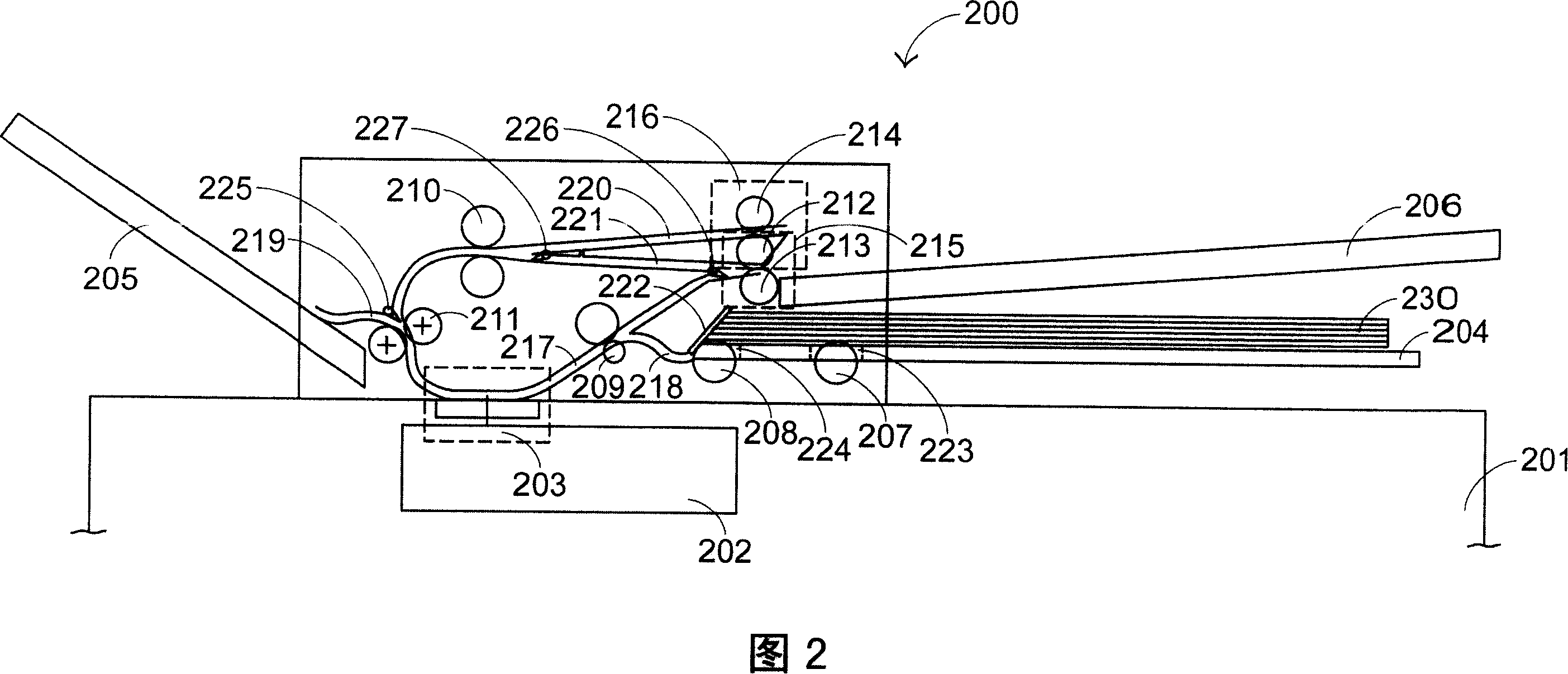
[0045] Please refer to FIG. 2 , which is a schematic diagram of a preferred embodiment of the present invention. The double-sided scanning device 200 in FIG. 2 includes a flatbed scanner 201, a scanning module 202, a paper input tray 204, a first output tray 205, a second output tray 206, a paper pickup roller 207, a paper separation roller 208, a A paper feeding roller group 209, a second paper feeding roller group 210, a first paper output roller group 211, a second paper output roller group 215, a third paper output roller group 216, a paper feeding channel 217, a paper feeding channel 218, a A paper output channel 219 , a second paper output channel 220 , an overturning channel 221 , a paper separation friction plate 222 , a first paper output guide rod 225 , an overturn guide rod 226 and a second paper output guide rod 227 . The paper tray 204 includes a first opening 223 and a second opening 224 . The second paper output roller set 215 includes a driving wheel 212 and a...


PUM


Abstract

The utility model relates to a double-sided scanner, which is characterized in that two openings are arranged at the bottom of a feed box respectively, enabling a pickup roller and a combing roller pass through the opening, thereby the double-sided scanner begins to scan from the bottom of a pile of documents. The utility model has the advantage that a file of documents are scanned from the bottom using secondary double-sided scanning, therefore the scanned documents and the documents before scanning has the same order.

Description

technical field [0001] The invention relates to a double-sided scanning device, in particular to a double-sided scanning device with two scans. Background technique [0002] The main function of the scanner is to capture images to convert the content of paper documents into electronic documents by scanning, so that users can disseminate, organize or save them. As scanner technology matures, scanners are becoming more and more popular. [0003] The earliest scanners can only scan images on one side of a document. If you want to scan images on both sides of a document, you must manually turn the document over so that the scanner can scan the image on the other side of the document. In view of the fact that it is too troublesome to turn over manually, a double-sided scanning device has appeared. [0004] A general double-sided scanning device includes a flatbed scanner and an automatic paper feeder installed on the flatbed scanner. The automatic paper feeder is used to feed a...

Claims


Application Information

Patent Timeline
IPC IPC(8): H04N1/04
Inventor 王钟凯管建国
Owner PRIMAX ELECTRONICS LTD
Why Eureka
Try Eureka