Electrostatic testing apparatus

A technology of electrostatic detection and static electricity, applied in the direction of electrostatic field measurement, etc., can solve the problems of static detection ring failure, affecting product quality, wasting working time, etc., and achieve the effect of eliminating the risk of injury, saving labor costs, and low production costs

Inactive Publication Date: 2008-02-27
DELTA ELECTRONICS POWER (DONGGUAN) CO LTD +1
View PDF0 Cites 5 Cited by
  • Summary
  • Abstract
  • Description
  • Claims
  • Application Information

AI Technical Summary

Problems solved by technology

However, this method wastes working time, and each worker must start working after the measurement, so everyone has several times a day to wait for the measurement and the time to be measured
In addition, there

Method used


Image

  • Electrostatic testing apparatus

Examples


Embodiment Construction

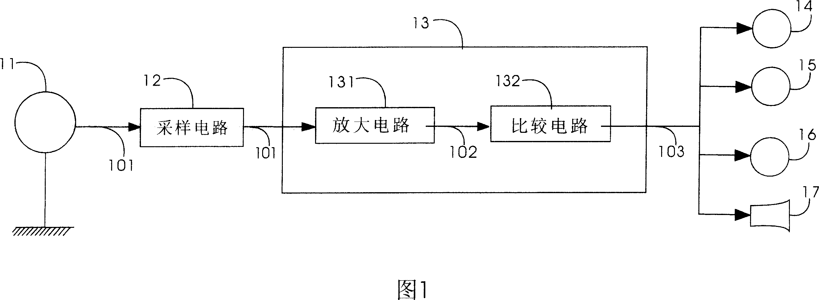
[0017] With reference to Fig. 1, one embodiment of the present invention, it is a static detection device 1, comprises a static detection ring 11, a sampling circuit 12, a processing circuit 13, a green light-emitting diode 14, a yellow light-emitting diode 15, a Red LED 16, a speaker 17, a switch (not shown) and a static detection ring jack (not shown). The processing circuit 13 further includes an amplification circuit 131 and a comparison circuit 132 .

[0018] When a user wants to detect the possible static electricity content of his body, he will wear the static detection ring 11, connect the body with the static detection ring 11, and connect the static detection ring 11 to a grounding terminal. Next, turn on the switch to activate the static electricity detection device 1 . On the other hand, the sampling circuit 12 is also connected to the static detection ring 11 for sampling a sample static signal 101 from the user's body through the static detection ring 11 .

[0...


PUM


Abstract

The invention discloses a static voltage detector. It includes a static detecting ring, a sampling circuit and a treatment circuit. The static voltage detector is connected with a user and a ground connecting end. The sampling circuit is to sample the static signal by the user. The treatment circuit can generate a treating result according to the user, the static detector and the ground connecting end.

Description

technical field [0001] The present invention relates to a static detection device; in more detail, it relates to a static detection device which can indicate the connection state. Background technique [0002] In the electronics industry, in order to prevent the static electricity carried by the user's body from causing damage to the electronic components it touches, most of them require the user to install a static detection ring on the body and ground the static detection ring to ground the static electricity. The static electricity carried by the body is conducted to the ground to eliminate the possible damage caused by static electricity. However, the electrostatic detection loop needs to be well connected to the ground to function. Therefore, it is necessary to measure to confirm that the electrostatic detection loop is connected well. Sometimes it needs to be measured once a day, and sometimes it needs to be measured several times a day. Like this, not only waste man-...

Claims


Application Information

Patent Timeline
IPC IPC(8): G01R29/12
Inventor 李丽
Owner DELTA ELECTRONICS POWER (DONGGUAN) CO LTD
Why Eureka
Try Eureka