Artificial finger

A finger and artificial technology, applied in the field of prosthetics, can solve the problems of work and life that cannot be solved, inconvenience, and unsightly

Inactive Publication Date: 2008-03-26
李明浩
View PDF0 Cites 10 Cited by
  • Summary
  • Abstract
  • Description
  • Claims
  • Application Information

AI Technical Summary

Problems solved by technology

Once a person loses his fingers, it is not beautiful, but also brings inconvenience to life
From an aesthetic point of view, people have designed artificial fingers that cannot move, bu...

Method used


Image

  • Artificial finger

Examples


Embodiment Construction

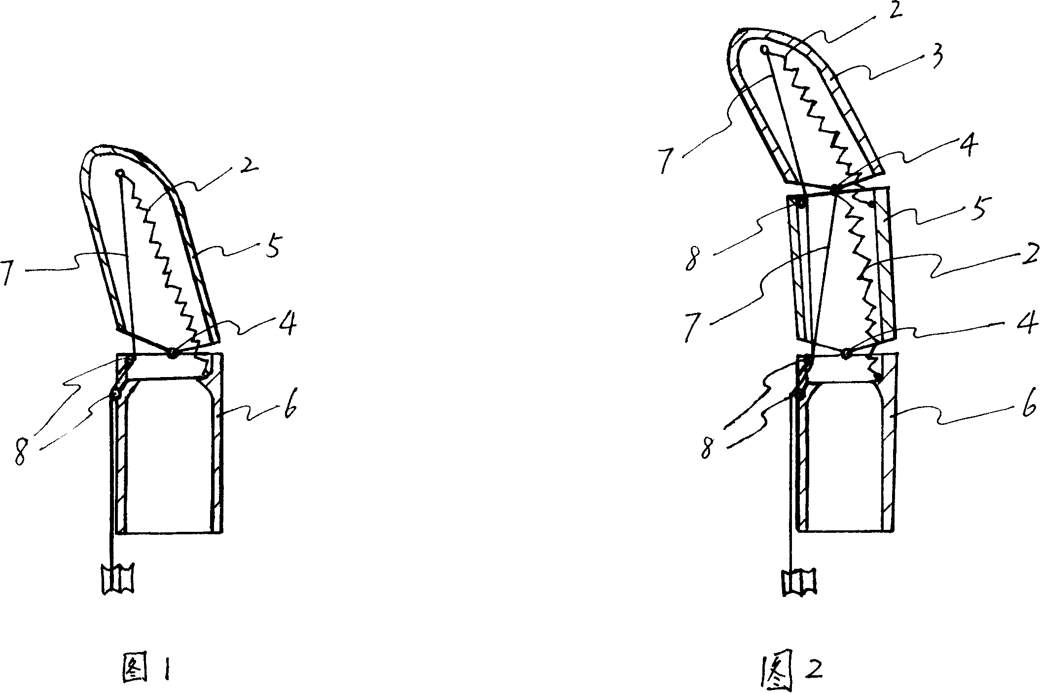
[0011] Figure 1 shows a structure of the artificial finger of the present invention. A hinge 4 is provided in the middle of the upper end of the fixed finger 6, the hinge 4 is connected to the movable finger 5, and the upper end of the movable finger 5 is provided with a pull wire 7 and a spring 2. 6 The upper end is led out inside, the other end of the tension spring 2 is fixed on the outer side of the upper end of the fixed finger 6, a pulley 8 can be set at the position where the fixed finger 6 leads out the cable 7, and the leading end of the cable 7 is also provided with a female buckle. The female buckle is fixed at the wrist. , The sub buckle is tied around the pull cord 7, and at the same time, a glove that matches the shape and skin color of the hand of the disabled can be set on the outside of the finger. At this time, the female buckle can be fixed on the glove corresponding to the wrist.

[0012] Figure 2 shows another type of structure of the artificial finger of the ...


PUM


Abstract

The present invention discloses an artificial finger, and it is characterized by that it has a fixed finger and a movable finger, said fixed finger is connected with its movable finger by means of hinge, the upper end point of said movable finger is equipped with a pull wire and a spring, said pull wire is led out from the fixed finger and another end of said spring is fixed on the fixed finger. Said invention also provides its concrete operation method.

Description

Technical field [0001] The present invention relates to a prosthesis, and directly relates to an artificial finger. Background technique [0002] In industrial production, it is common to see scenes of operators being squeezed or cut off their fingers. Once a person loses his finger, it is unsightly and brings inconvenience to life. From the aesthetic point of view, people have designed fake fingers that will not move, but after wearing them, the disabled only meet the psychological requirements of not being looked at by others, and the inconvenience in work and life cannot be solved. Summary of the invention [0003] The purpose of the present invention is to provide an improved artificial finger, which can effectively overcome the inconvenience in work and life that the existing artificial finger can only be in a stationary state. [0004] The purpose of the present invention is achieved in this way. The artificial finger has a fixed finger, which is characterized in that the ...

Claims


Application Information

Patent Timeline
IPC IPC(8): A61F2/54
Inventor 李明浩李明旺李明明李明蕾周脉玲
Owner 李明浩
Why Eureka
Try Eureka