
Eureka
For R&D, Eureka makes reading and utilizing patents & technical documents easy.
Eureka AIR
Designed for self-driven R&D workflows. Generate viable solutions, solve complex R&D challenges, empower your innovation with AI.

Eureka Materials
Designed for material experts only. Revolutionize your material R&D, from search, analyze, to developing new materials.

TechResearch
Generate reliable direction feasibility study reports for your R&D in just a few steps.

TechSeek
Discover and master advanced knowledge NOW. Basics, ideas, possibilities, all at once.

TechMind
As an expert in R&D Theories, TechMind can generates customized viable solutions instantly.

TechRisk
Analyze your overall solution with one click, know your potential R&D risks in advance.

TechMonitor
Get weekly tech updates, stay abreast of the latest tech innovations and key insights.
Lens driving device and imaging device using the same
A lens driving device and driving source technology, applied in installation, optics, instruments, etc., can solve the problems of insufficient shortening of length and inability to achieve miniaturization, and achieve the effect of realizing miniaturization and reducing space
- Summary
- Abstract
- Description
- Claims
- Application Information
AI Technical Summary
Problems solved by technology
Method used
Image

Examples
Embodiment Construction
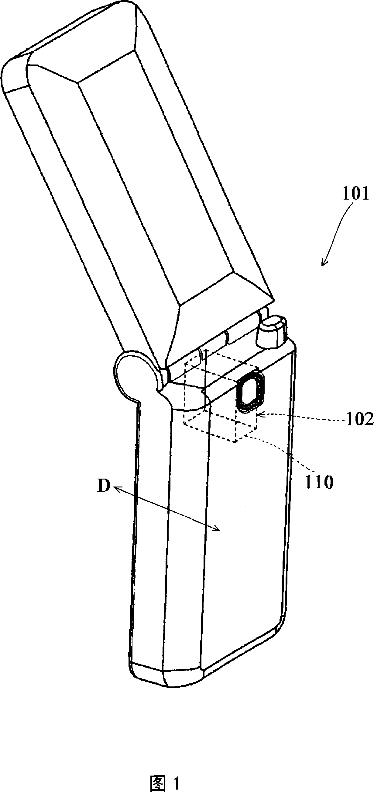
[0058] Embodiments of the present invention will be described below with reference to the drawings. FIG. 1 is a schematic diagram showing the appearance of a mobile phone 101 according to an embodiment of the present invention. The mobile phone 101 is a mobile phone with a camera function. Furthermore, the mobile phone 101 has a camera unit 102 having a box-shaped housing 110, a lens unit and a camera element (CCD) disposed in the housing 110. In addition, the camera module 102 is configured to image reflected light of an object through an imaging element according to a user's operation, convert it into an electrical signal, and output the electrical signal to an A / D converter or the like.
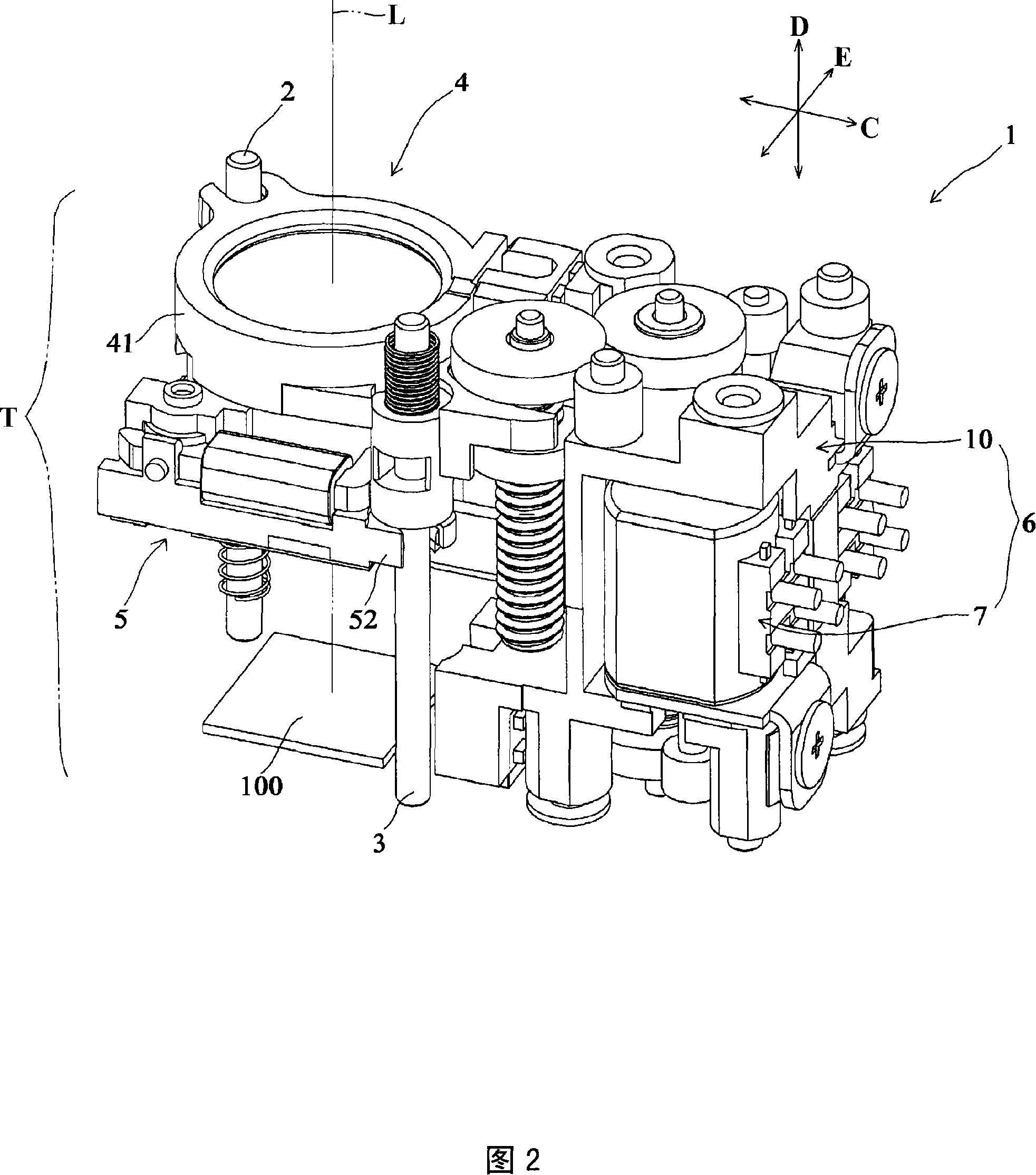
[0059] FIG. 2 is a perspective view of the lens unit 1 . The lens unit 1 has a first guide rod 2 , a second guide rod 3 , a first lens group holding member 4 , a second lens group holding member 5 , and a lens driving device 6 .
[0060] The guide rods 2 and 3 are guide members for guid...
PUM
 Abstract
Description
Claims
Application Information
 - R&D Engineer
- R&D Manager
- IP Professional
- Industry Leading Data Capabilities
- Powerful AI technology
- Patent DNA Extraction
Browse by: Latest US Patents, China's latest patents, Technical Efficacy Thesaurus, Application Domain, Technology Topic, Popular Technical Reports.
© 2024 PatSnap. All rights reserved.Legal|Privacy policy|Modern Slavery Act Transparency Statement|Sitemap|About US| Contact US: help@patsnap.com