

Zoom lens system and electronic image pickup apparatus using the same
A technology of zoom lens and image side, which is applied in TV, electrical components, image communication, etc., and can solve the problems that are not conducive to miniaturization
- Summary
- Abstract
- Description
- Claims
- Application Information
AI Technical Summary
Problems solved by technology
Method used
Image

Examples
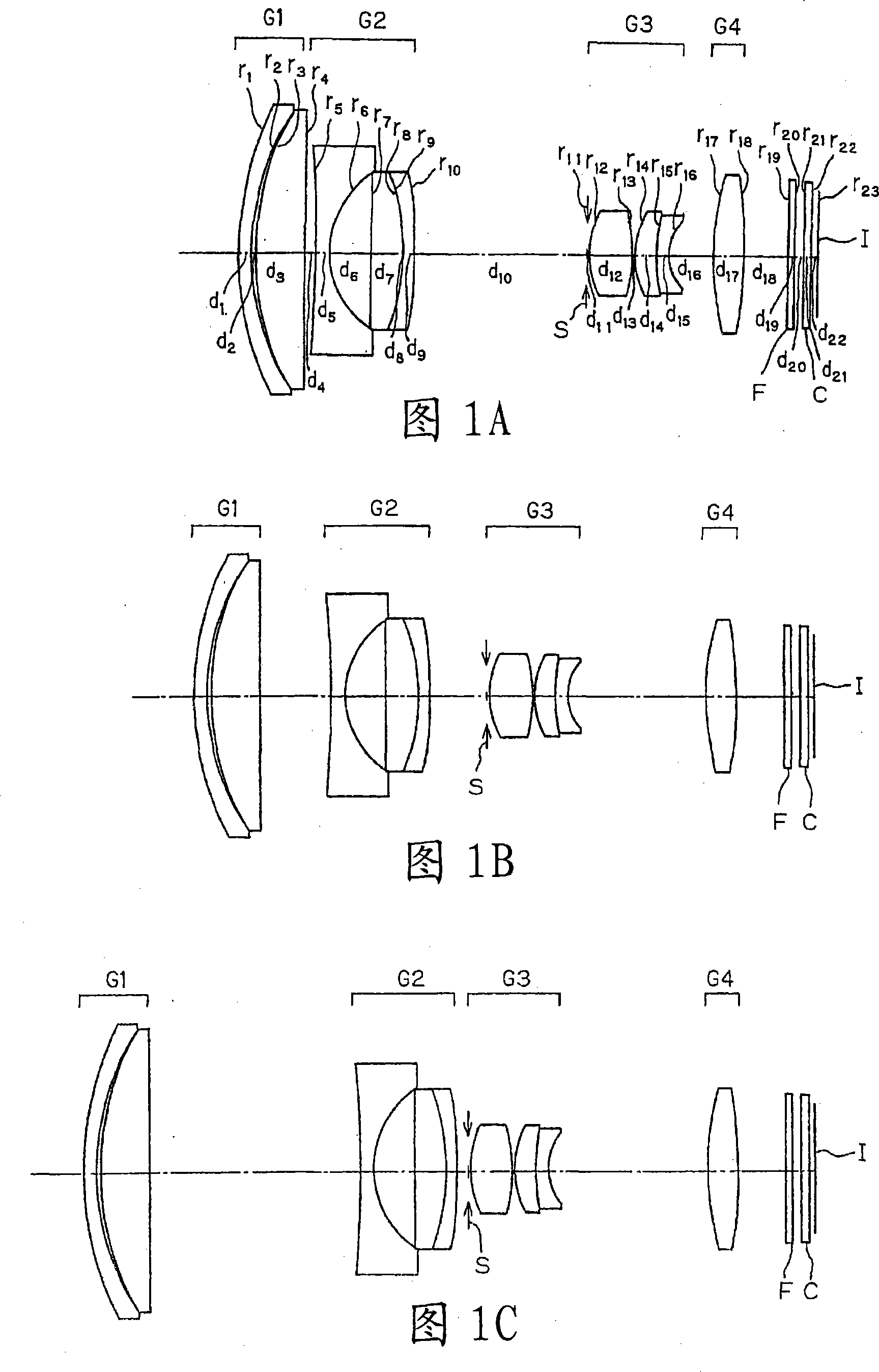
Embodiment 1
[0588] r 1 =19.996 d 1 =0.80n d1 = 1.92286 v d1 =18.90
[0589] r 2 =15.394 d 2 =0.26
[0590] r 3 =17.278 d 3 =3.11n d2 = 1.76802 v d2 =49.24
[0591] r 4 =534.344 d 4 = variable
[0592] r 5 =-58.703(AS)d 5 =0.82n d3 = 1.88300 v d3 =40.76
[0593] r 6 =5.969(AS)d 6 =2.65
[0594] r 7 =-431.058 d 7 =1.95n d4 =2.00170V d4 =20.64
[0595] r 8 =-14.597 d 8 =0.07
[0596] r 9 =-13.708 d 9 =0.67n d5 =1.81600 v d5 =46.62
[0597] r 10 =-67.948(AS)d 10 = variable
[0598] r 11 =∞(S)d 11 =0.10
[0599] r 12 =5.491(AS)d 12 =2.70n d6 = 1.58913 v d6 =61.14
[0600] r 13 =-11.075(AS)d 13 =0.10
[0601] r 14 =5.503 d 14 =1.38n d7 = 1.59201 v d7 =67.02
[0602] r 15 =13.913 d 15 =0.80n d8 =2.00069 v d8 =25.46
[0603] r 16 =3.463 d 16 = variable
[0604] r 17 =19.919(AS)d 17 =2.07n d9 =1.74330 v d9 =49.33
[0605] r 18 =-25.922 d 18 = variable
[0606] r19 =∞d 19 =0.40 n d10 =1.54771V d10 =62.84
[0607] r 20 =∞d 20 ...
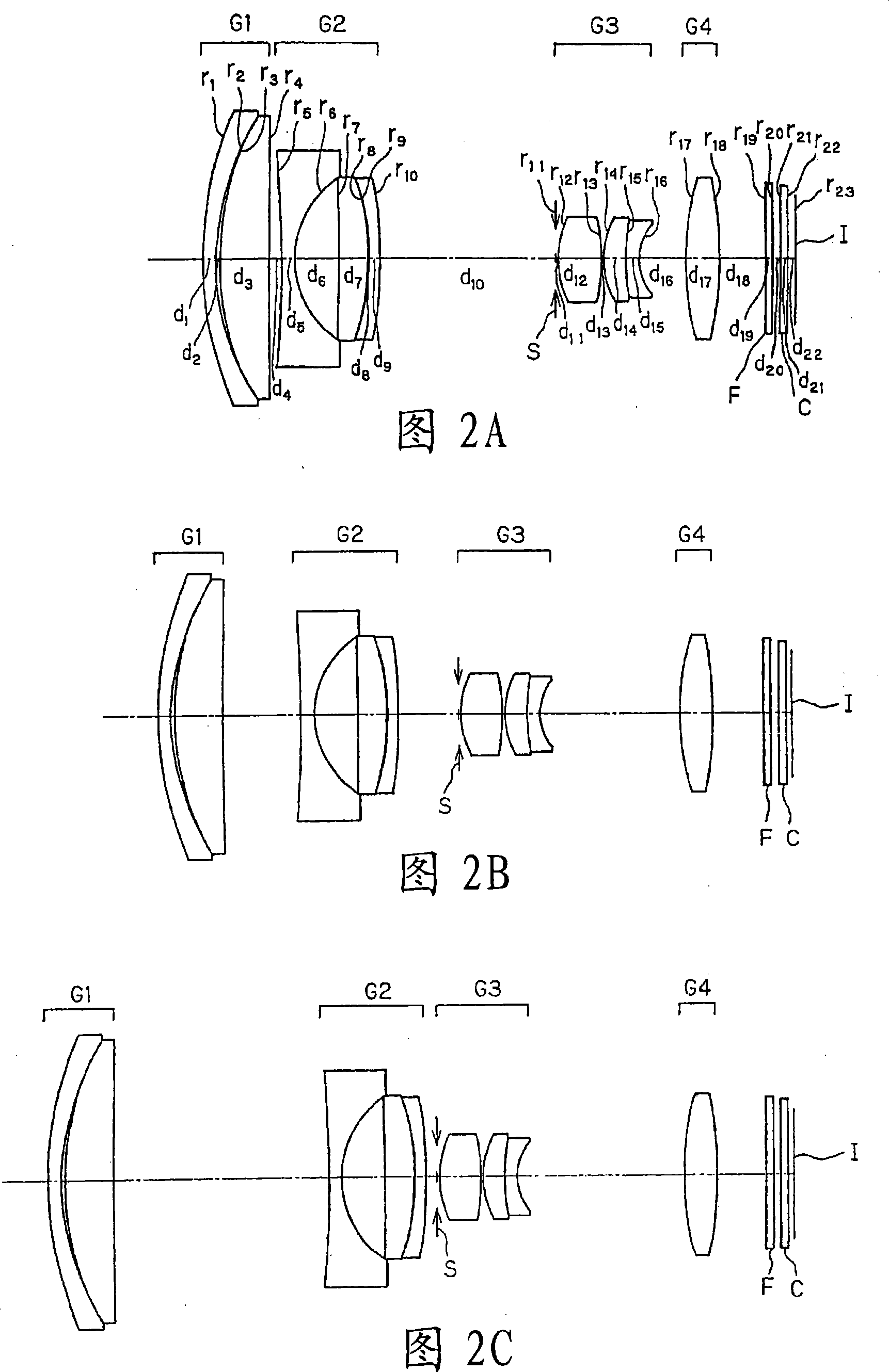
Embodiment 2
[0646] r 1 =23.279 d 1 =0.80n d1 = 1.92286 v d1 =18.90
[0647] r 2 =16.155 d 2 =0.18
[0648] r 3 =17.729 d 3 =3.05n d2 = 1.85719 v d2 =43.01
[0649] r 4 =577.289 d 4 = variable
[0650] r 5 =-57.796(AS)d 5 =0.80n d3 =1.83481V d3 =42.71
[0651] r 6 =5.963(AS)d 6 =2.79
[0652] r 7 =-136.071d 7 =1.78n d4 = 1.94595 v d4 =17.98
[0653] r 8 =-16.198 d 8 =0.09
[0654] r 9 =-14.697d 9 =0.68n d5 =1.83481V d5 =42.71
[0655] r 10 =-44.810(AS) d 10 = variable
[0656] r 11 =∞(S)d 11 =0.10
[0657] r 12 =5.548(AS)d 12 =2.70n d6 = 1.58913 v d6 =61.14
[0658] r 13 =-10.984(AS) d 13 =0.10
[0659] r 14 =5.510d 14 =1.36n d7 = 1.59201 v d7 =67.02
[0660] r 15 =13.333 d 15 =0.80n d8 =2.00069 v d8 =25.46
[0661] r 16 =3.476 d 16 = variable
[0662] r 17 =19.243(AS)d 17 =2.07n d9 =1.74330 v d9 =49.33
[0663] r 18 =-28.285 d 18 = variable
[0664] r 19=∞ d 19 =0.40 n d10 =1.54771V d10 =62.84
[0665] r 20 =∞d 20 ...
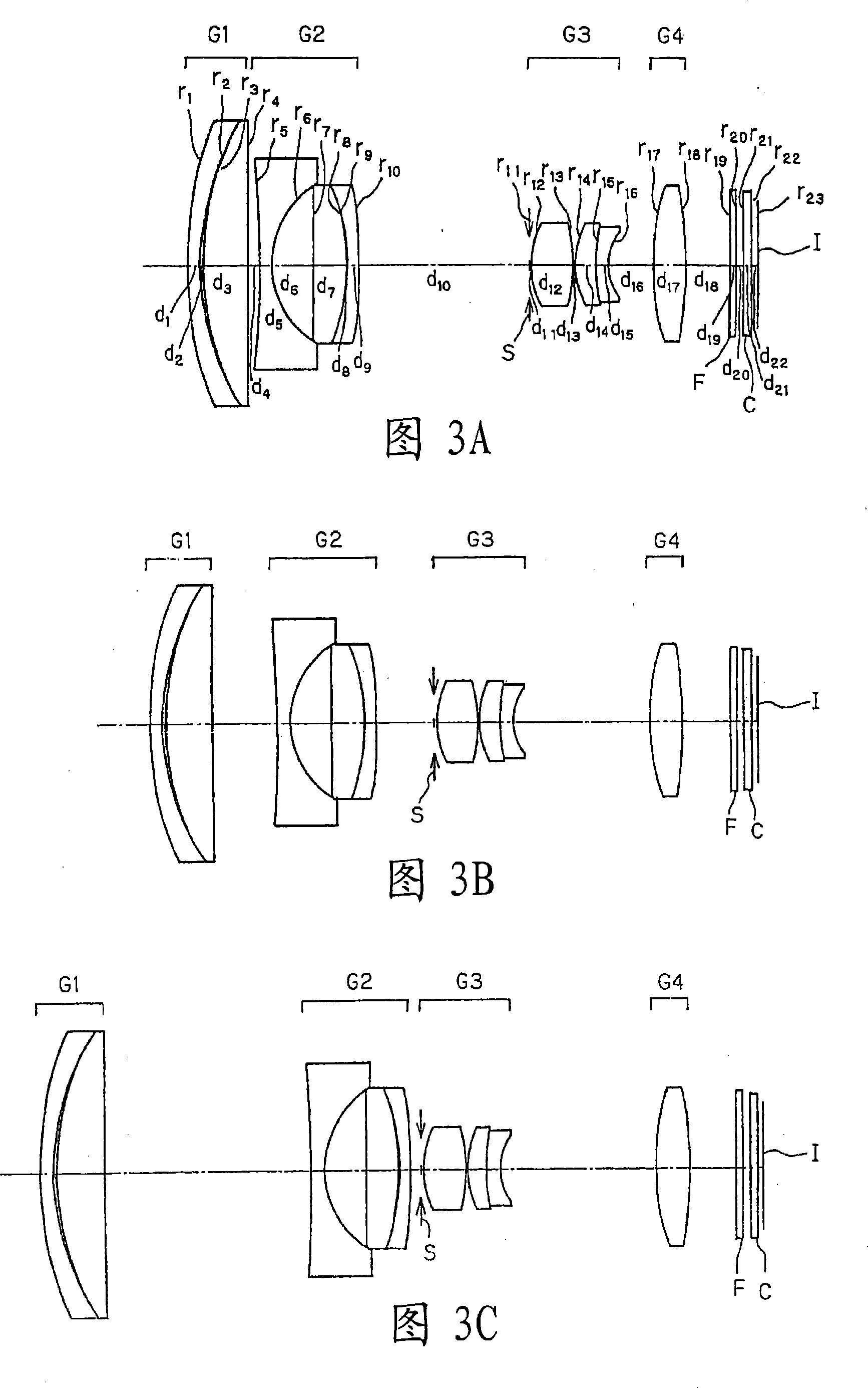
Embodiment 3
[0704] r 1 =24.343 d 1 =0.80n d1 = 1.92286 v d1 =18.90
[0705] r 2 =16.189 d 2 =0.16
[0706] r 3 =17.639 d 3 =3.05n d2 = 1.88300 v d2 =40.76
[0707] r 4 =598.304 d 4 = variable
[0708] r 5 =-58.725(AS)d 5 =0.82n d3 = 1.88300 v d3 =40.76
[0709] r 6 =6.041(AS)d 6 =2.60
[0710] r 7 =407.018 d 7 =2.01n d4 =2.00170V d4 =20.64
[0711] r 8 =-14.787d 8 =0.08
[0712] r 9 =-13.762 d 9 =0.68n d5 =1.83481V d5 =42.71
[0713] r 10 =-88.096(AS)d 10 = variable
[0714] r 11 =∞(S)d 11 =0.10
[0715] r 12 =5.462(AS)d 12 =2.70n d6 = 1.58913 v d6 =61.14
[0716] r 13 =-11.013(AS)d 13 =0.10
[0717] r 14 =5.530d 14 =1.36n d7 = 1.59201 v d7 =67.02
[0718] r 15 =13.426 d 15 =0.80n d8 =2.00069 v d8 =25.46
[0719] r 16 =3.443 d 16 = variable
[0720] r 17 =19.462(AS)d 17 =2.07n d9 =1.74330 v d9 =49.33
[0721] r 18 =-27.222d 18 = variable
[0722] r 19 =∞ d 19 =0.40nd10 =1.54771V d10 =62.84
[0723] r 20 =∞ d 20 =0.5...
PUM
 Abstract
Description
Claims
Application Information