

Ring shaped inner sliding track and sliding block wind-driven engine with steadying line
A technology of stabilizing cables and circular rings, which is applied in the direction of wind power engines, engines, machines/engines, etc., and can solve problems such as difficult production, high price, and heavy weight of wind blades
- Summary
- Abstract
- Description
- Claims
- Application Information
AI Technical Summary
Problems solved by technology
Method used
Image

Examples
Embodiment Construction
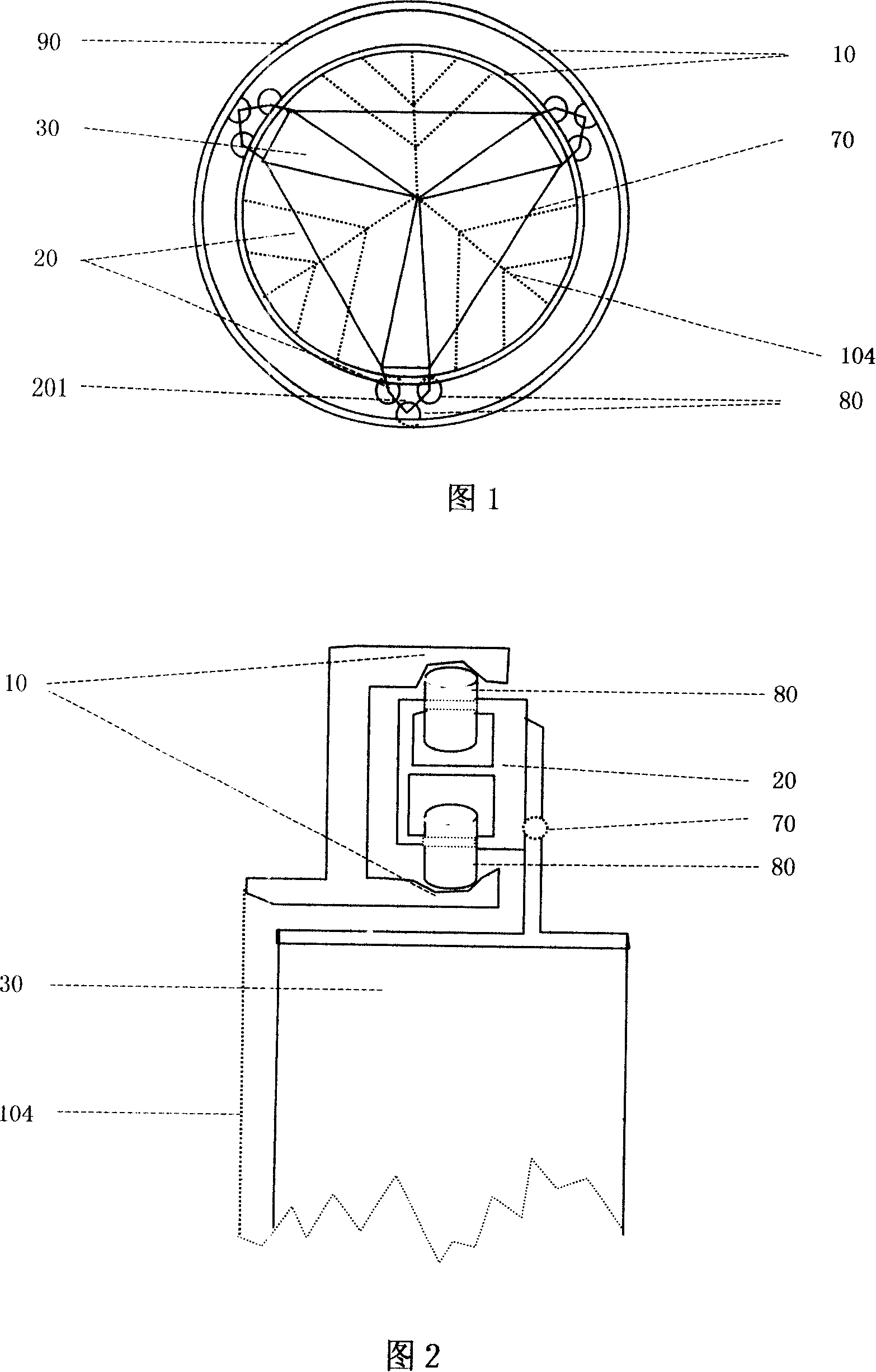
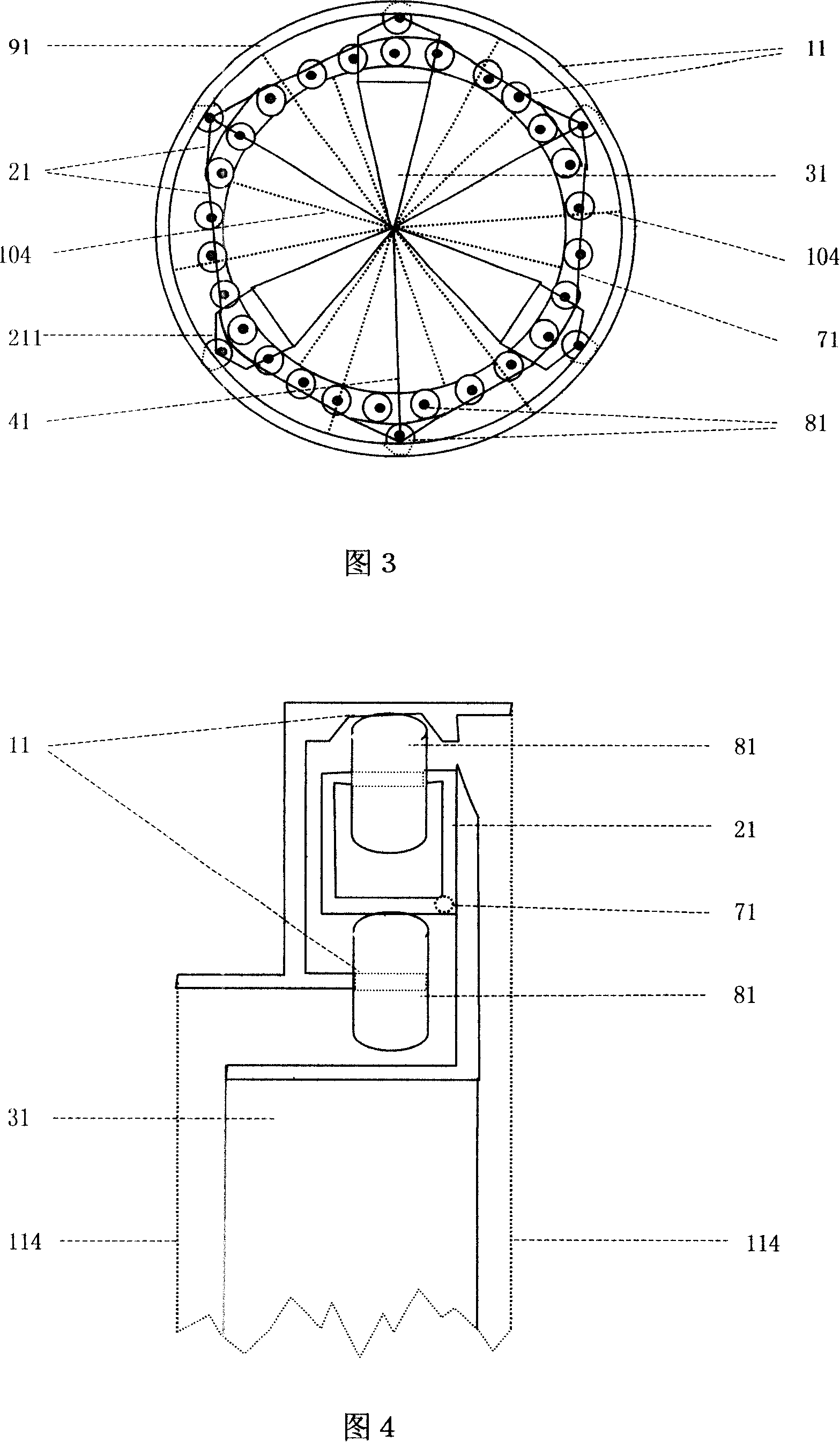
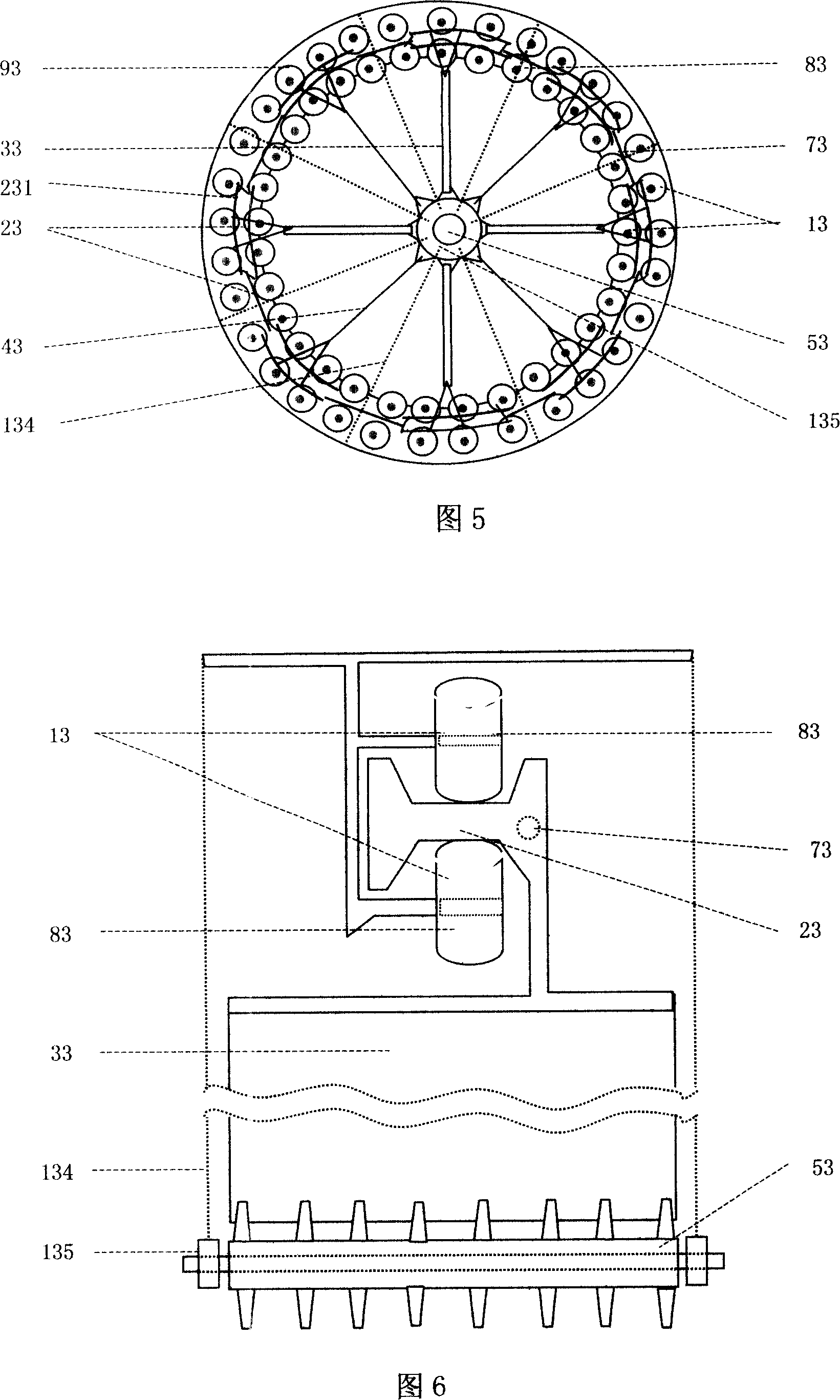
[0096] In this specification, the so-called "circular inner slide rail with stabilizing cable" is composed of two parallel circular rings, and the stabilizing cable can be fixed on the two circular rings, or on one of the circular rings . The stabilizing cable can also be fixed on the support frame or the support ring that directly provides support for the two rings, and provides tension for the two rings by being connected with the support frame or the support ring. The stabilizing cable can be arranged on one side of the annular inner slide rail, or can be arranged on both sides of the annular inner slide rail simultaneously. Except that the planes determined by the two rings forming the circular inner slide rail should be parallel, the distance between any point on the sides of each ring and the sides of other rings is constant. One ring provides support and slideway for the outside of the slider with the inside, and the other ring provides support and slideway for the ins...
PUM
 Abstract
Description
Claims
Application Information